
Highwayman Pipe Tuning: exemplified for the Yamaha TD3 250cc twin
Achieving a specific tuning goal with pipe design. The goal was to achieve equal or greater power while moving the red-line from ~13,000 RPM to a max of 11,000 RPM. The pipes on the bike kept wanting to pull way past 11000 RPM, and the owner wanted to keep the power below that to preserve crankshaft life, while not loosing race winning power!
Report on pipe tuning for an otherwise stock Yamaha TD3 250
By -Jeff Henise
A Yamaha TD3 250 road racer was brought to me in stock condition (stock cylinders and porting, stock heads, stock carbs, stock crank pistons, stock ignition and cases) the only modification being a set of aftermarket pipes. The owner didn’t like how the power came on around 11000 RPM and seemed to keep pulling to 13000 or more.
While using high RPM will probably produce the best peak horse power the extra revs are hard on components, and crankshaft life is known to be significantly shorted on these bikes above 11000 RPM. So our goal was to try to make a set of pipe that would increase the mid range and upper mid range, effectively moving the usable power to a range below 11000 RPM, without sacrificing power.
I will show the final results first in case you don’t want to read all the details.
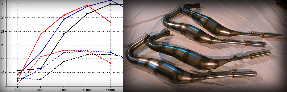
I designed and made two sets of pipes (Image 1) to try and achieve the above goal: “Highwayman Long pipes” and “Highwayman Short Pipes.” The short pipes worked exactly as planned: boosting mid range and moving the red line to 11000 RPM without loosing peak power. The long pipes were more of an extreme case to see how low of an RPM we could make power, there were not successful because the port timings in the cylinders are tuned for higher RPM and simply arent a good match for low RPM power. Dyno runs of both of these pipes, along with the pipes provided with the bike are show below in Chart 1.
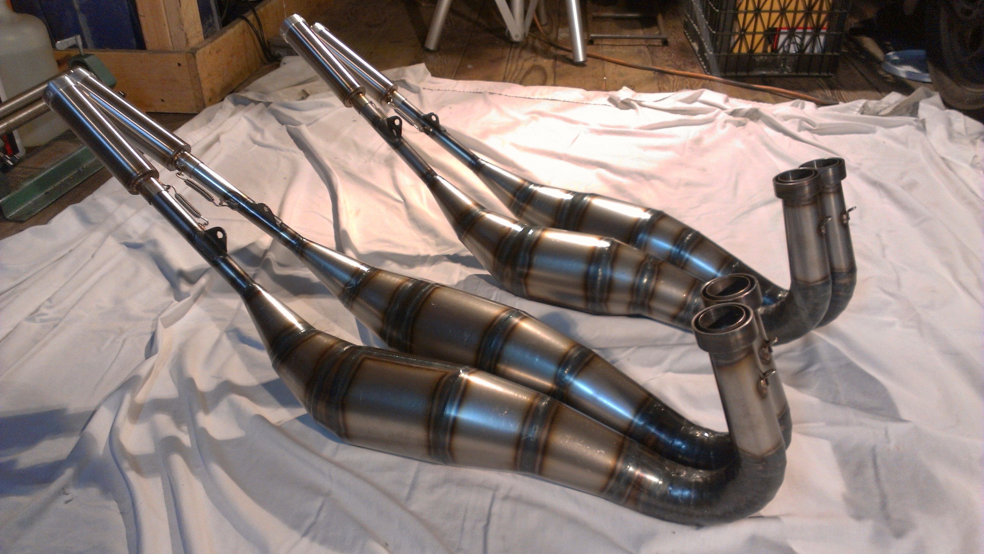
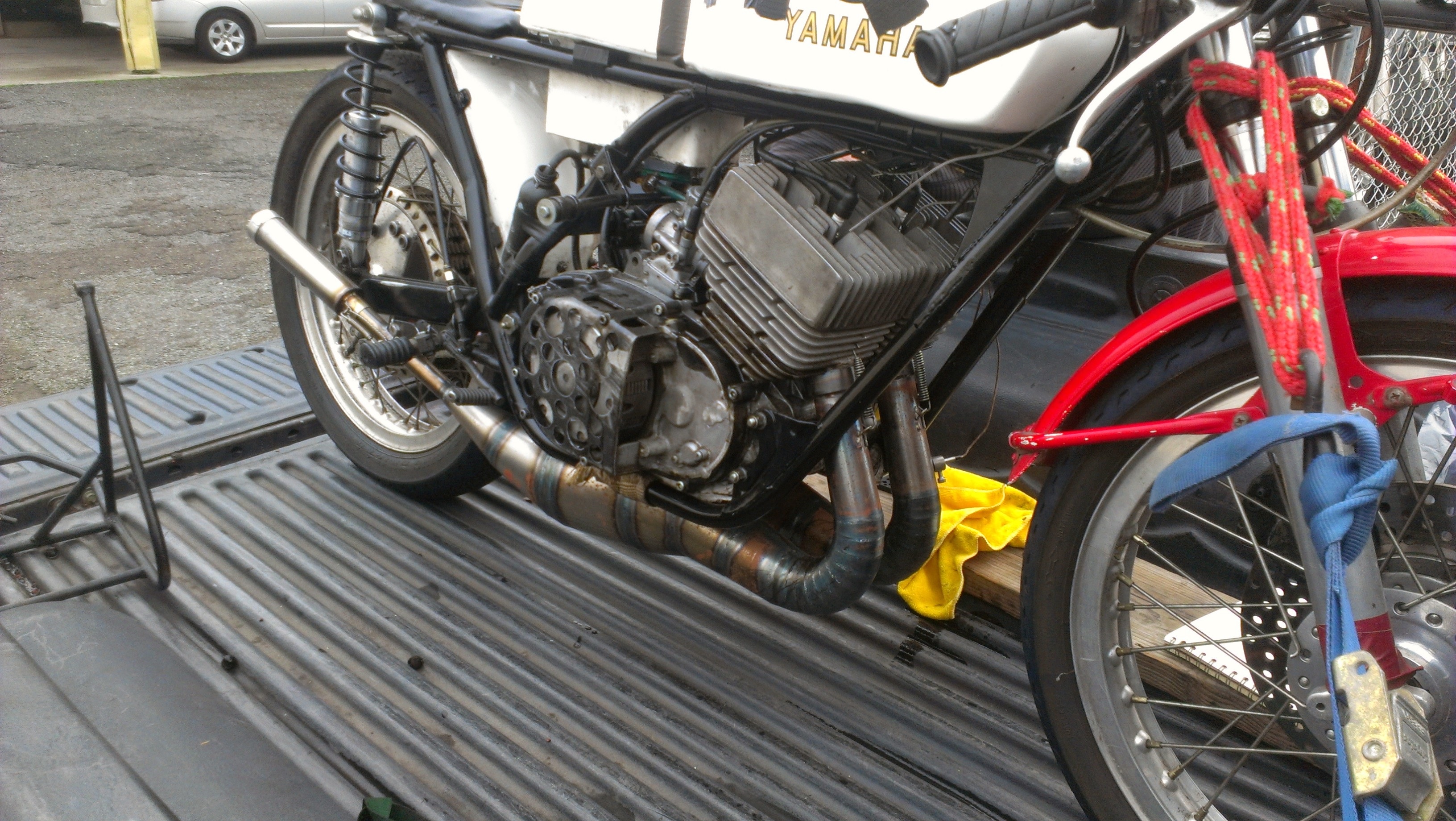
Image 1. Highwayman pipes fort the TD3.
I use Factory Pro – Wheelsmith Racing for Dyno Testing in San Rafael , CA www.factorypro.com/index.htm
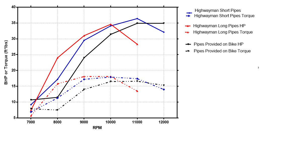 Chart 1. Dyno results for the aftermarket pipes supplied with the bike (Black) and the new Highwayman pipes that were designed around them. The Highwayman short pipes (Blue) achieve the goal of moving the usable power to below 11000 RPM. A major increase in power was achieved below 11k with a small amount of useful over-rev retained. An attempt to drop the usable power even lower (Red, Highwayman long pipes) resulted in unacceptable loss of top end power.
We did a small amount of testing with silencer can inserts, and jetting on the dyno. These were small changes, meaning main jet changes of about +/- 1 size, and the stinger tube within the silencer can +/- about 1-2 mm in diameter. The results of these tests are shown below in Chart 2. Leaner jetting and tighter cans create more Area Under the Curve (AUC) around peak power, mainly in the form of enhanced over-rev.
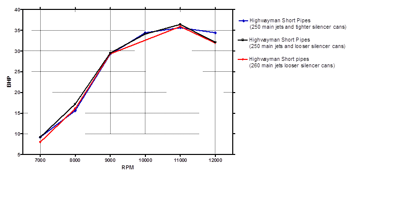 Chart 2. Compares the effect of jetting and back pressure on the Highwayman short pipes. Richer jetting (Red), leaner but safe jetting (Black), and leaner jetting with more back pressure (Blue, tighter silencer cans). Leaner jetting gives a marginal power increase across the whole range. Increasing the pipes back pressure (Blue) creates more area under the curve past peak power at the expense of a small loss of bottom end and peak power.
Below are notes on using exhaust gas temperature (EGT) data for tuned length calculations: The Highwayman Method.
A critical parameter in two stroke pipe design is the gas temperature within the pipe. The gas temperature effects the speed of sound within the pipe, and in turn the time it takes for the sonic pressure waves that we are trying to harness to “valve” the exhaust port and create suction to drive scavenging (the point of the pipe!) to arrive at the exhaust port at the proper time. Knowing the average gas temperature within the pipe is required to predict the pipe’s tuned length, that sets the peak power RPM.
If you read old school two stroke tuning manuals like Gordon Jennings or those in Tom Turner’s TSR software they advise to use the header temperature to calculate a pipe’s tuned length. This does work if the proper “fudge” factors are built into your tuned length equation. But in reality the header runs significantly hotter than the body of the pipe. In fact a majority of the pipe runs at the body temperature and not the header temperature. Therefore wave propagation is not constant within the pipe buy heavily weighted by the body temperature. Simply measuring the EGT at the header can lead to error in predicting tuned length, especially if you are comparing different scenarios that can effect the balance of heat between the header and body. For example: mild steel vs. stainless (heat propagates further in mild steel) or a pipe inside a fairing vs. outside in the wind, etc… For the most accurate estimate of tuned length the temperature must be known at various points along the pipe, under the exact operating conditions.
To study heat distribution in pipes I made a data logging system that could record pipe temperature from 4 positions along the pipe’s length. The photos below show two such sensors mounted in my TD3 test pipes for the Dyno day, and the data acquisition electronics mounted to the gas tank.
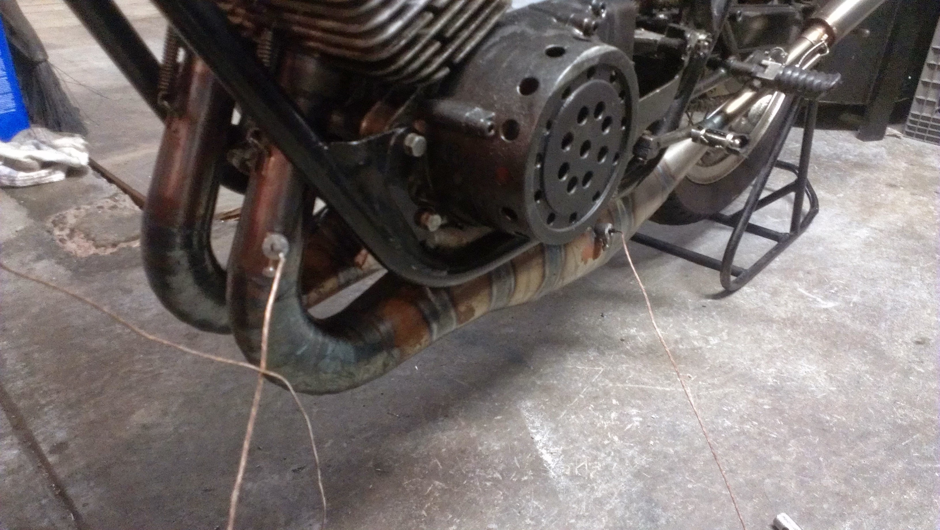
Image 2. Highwayman short pipes on the TD3, showing temperature sensors.
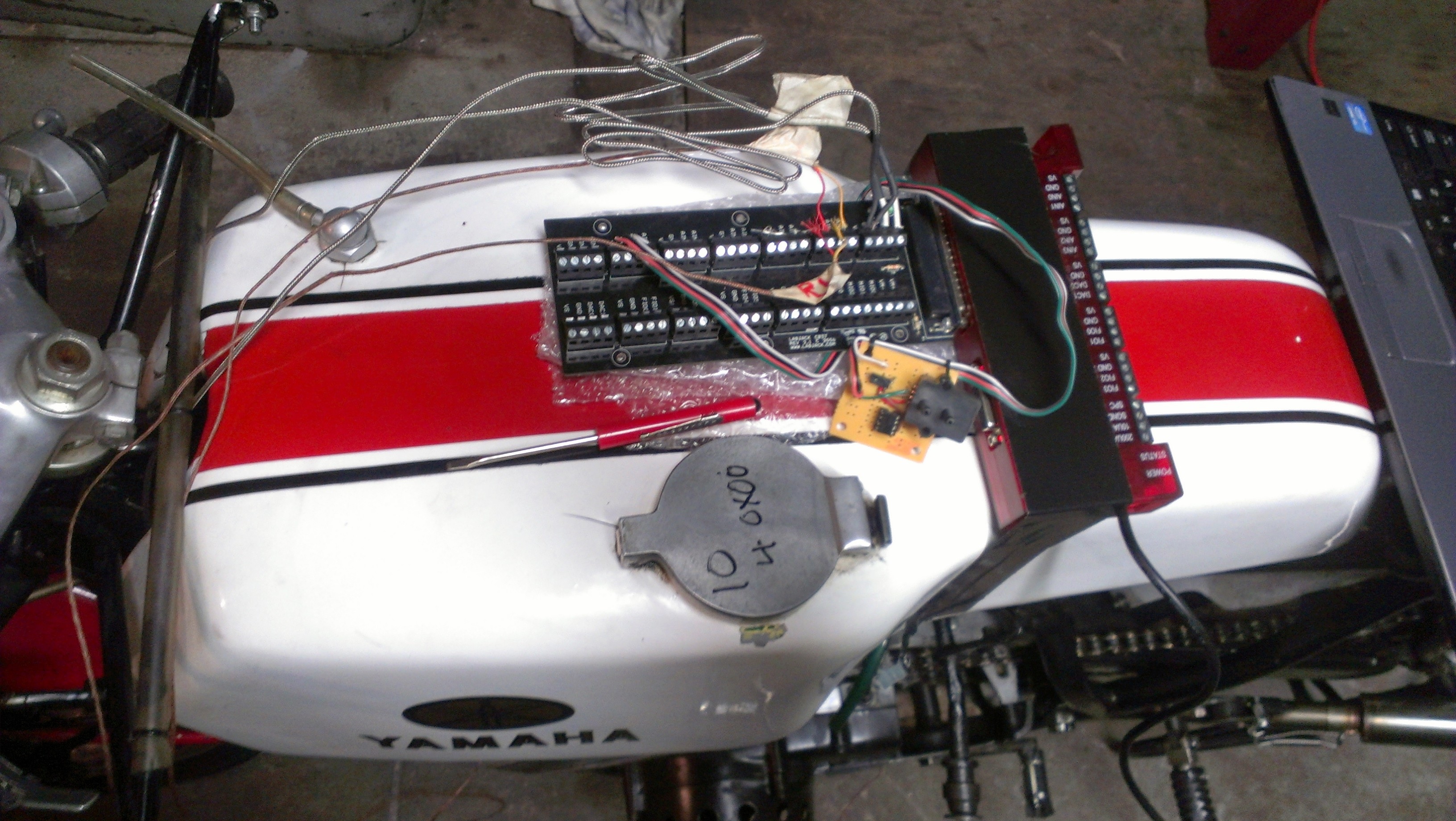
Image 3. DAQ card (Lab Jack U6 Pro) used for recording of CHT, EGT1, EGT2, barometric pressure, air temperature, and humidity. A program was made using DAQFactory software for data logging. Atmospheric conditions for Dyno testing day: Air temp = 22 oC, 62 % humidity, 1.043 Bar barometric pressure 1.223 kg/m^3 absolute air density.
The chart below shows data acquired from my custom program during a Dyno run. It is interesting to note how heat production directly parallels power production, illustrating how heat measurements alone can be used to predict maximum power in the absence of a Dyno, but that is another story 🙂
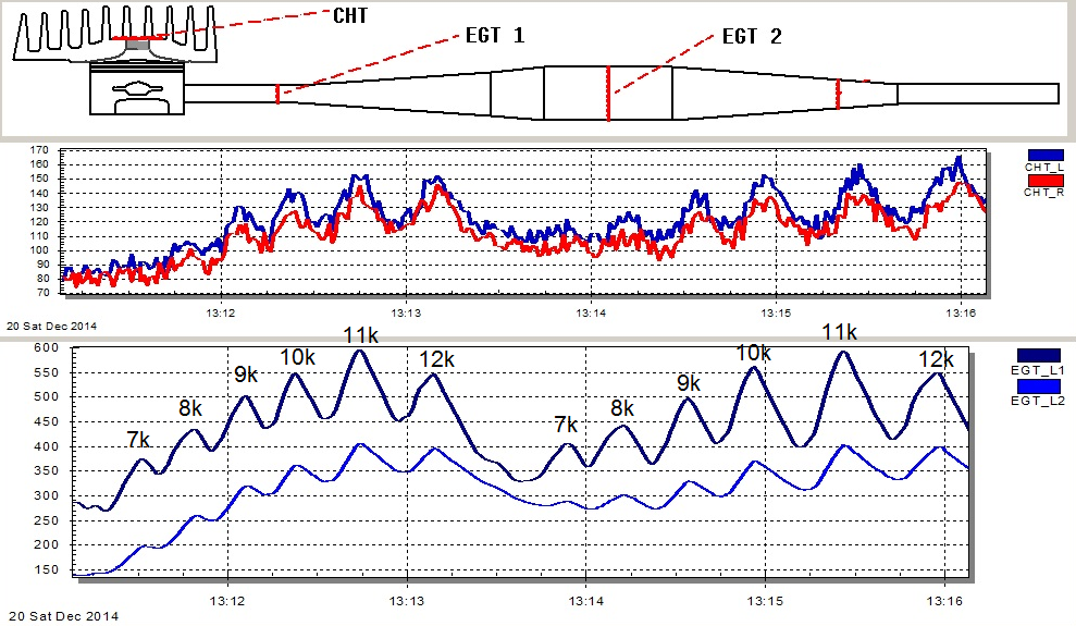
Chart 3. Temperature readings (oC) during a DYNO run of the Highwayman short pipes. Sustained load RPM’s are labeled (7k – 12k). Temperature correlates well with power. At peak power (11k RPM) the header exhaust gas temperature (EGT) is 590 oC or 1094 oF, this is right below the “healthy” limit of about 1200 oF. Exhaust gas analysis readings indicate that the mixture is slightly rich, one size leaner main jet would probably push it to the limit. The cylinder head temperature (CHT) at peak power was 160 oC or 320 oF, on the track I like to see the CHT stay below 375 oF with occasional peaks to ~420 oF. I suspect the CHT on this motor would raise under sustained racing load with this jetting.
After studying heat gradients in expansion chambers I came up with the method below of to use pipe temperature to calculate tuned length, and get the peak power RPM on target.
I have found from data logging experiments that the EGT near the stinger is equal to EGT2 (see Chart 3), it can also be seen that the header runs a lot hotter (see EGT1 in Chart 3). A good approximation of the bulk temperature in the pipe is made by assuming that 66% or 2/3 of the length of the pipe runs at the temp of EGT2 and that that 33% or 1/3 runs at EGT1.
The average EGT of the whole pipe based on this assumption is given by a weighted average:
EGTavg = [(66*EGT2) + (33*EGT1)]/100
Applying this equation to the temperatures in Chart 3 at 11000 RPM (near peak power) gives:
EGTavg = [(66*410) + (33*600)]/100 = 468.6 oC
The average speed of sound in the pipe will be closely related to temperature calculated as above, therefore this is the most relevant temperature for predicting overall tuned length.
To validate the use of this weighted average temperature to predict tuned length, we can take the above temperature value (468.6 oC) to solve Gordon Blair’s tuned length equation (Figure 1A, below) for the Highwayman Short pipes, and adjust the peak power RPM in the equation to predict the pipes length. The solution tells us that we need a pipe 860 mm long to produce a power peak at 10700 RPM (Figure 1B) with the weighted average EGT of 468.6 oC. The Highwayman Short pipes are in fact 867 mm long, in very good agreement with the theory, and in fact make peak power around 11000 RPM as seen from the Dyno tests. If the header temperature alone (1094 oF) was used in the equation it would predict a pipe that was way to long.
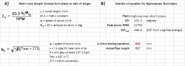
Figure 1. A) Tuned length calculations from Gordon Blair. B) Application of the equation to predicting tuned length of the Highwayman short pipes, using the weighted average temperature as the input.
If I am going to design pipes for a new motor, I used a weighted average EGT that I have measured from similar applications to predict the tuned length. That is in fact how these TD3 pipes came to be. Below (Chart 4) shows simulated power curves for my TD3 pipe designs compared to real Dyno data.
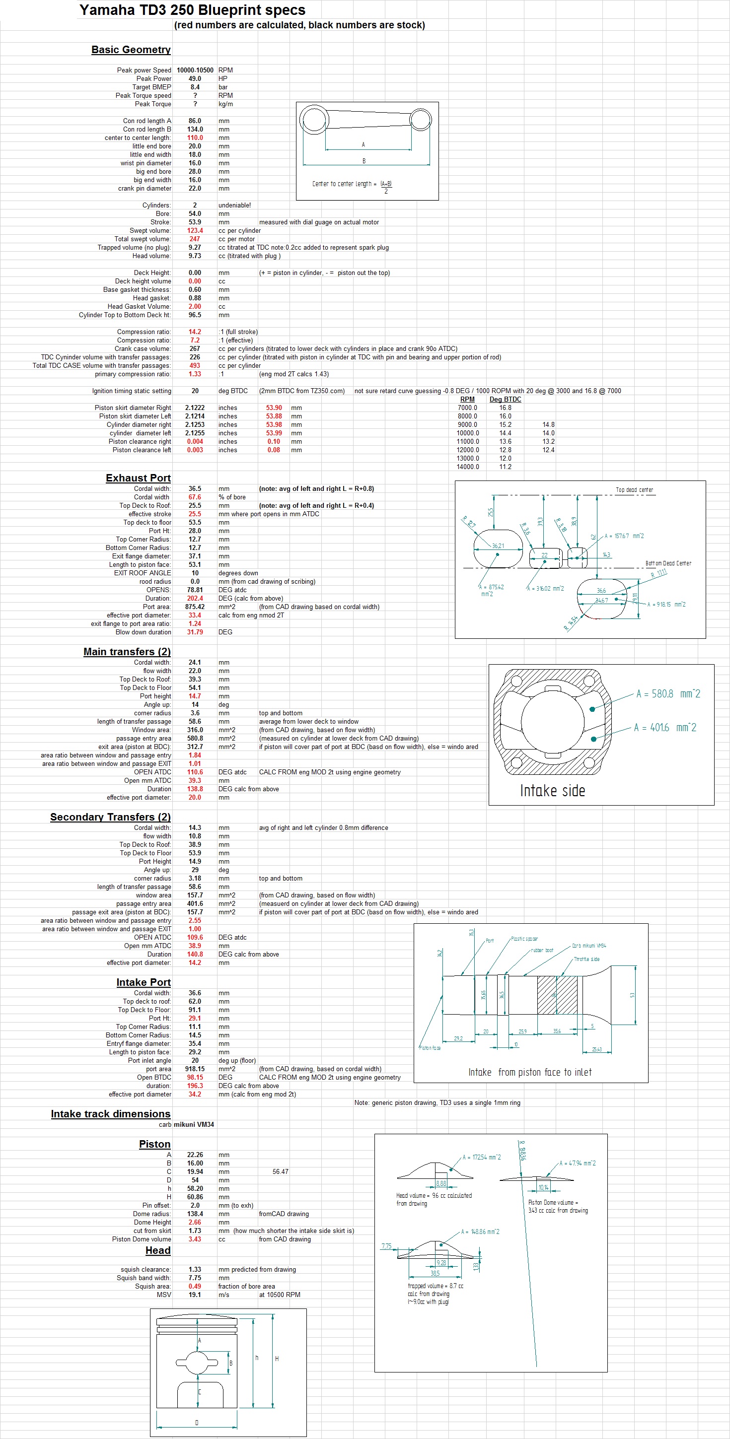
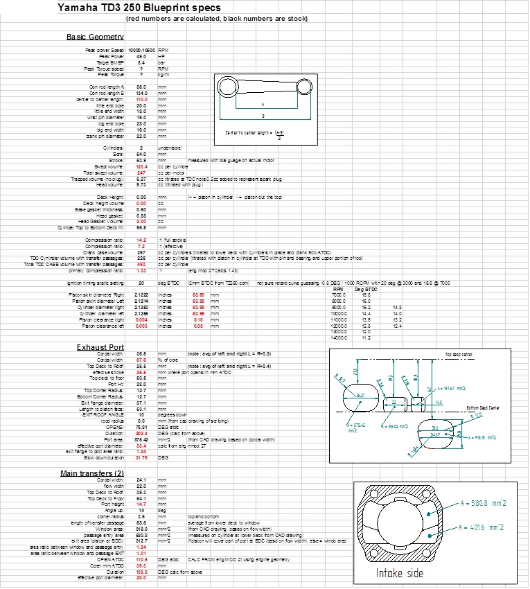
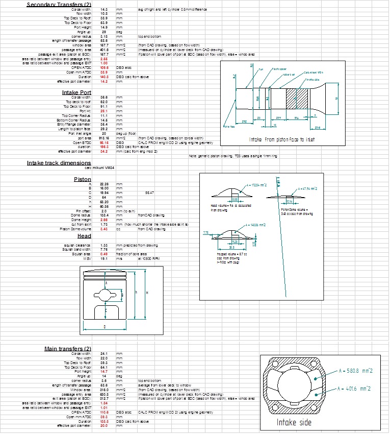
I use Engmod 2T software to design pipes and engines and simulate power curves. This is an elegant program composed by Neels van Niekerk (http://vannik.co.za/About.htm), that is basically a collection of Gordon Blair’s engine simulation programs (Design and Simulation of Two Stroke Engines) wrapped up into a neat user friendly application. It takes a LOT of careful measurements of the engine to accurately set up a simulation (see the “blue print specs” at the end of this article for an example). Note: In the chart below I slipped in data from the genuine Yamaha factory TD3 pipes.
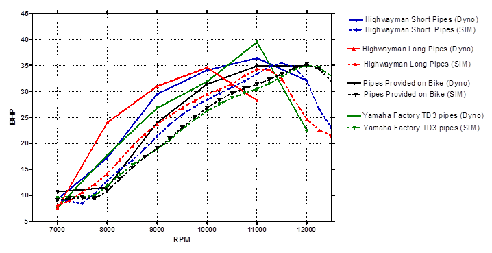
Chart 4. Dyno results and simulated power curves used for pipe design. Simulated power curves (dotted lines) from analysis of the pipes provided with the bike and from design of our improved pipes. These simulations were made with NO Dyno data in hand, they were created completely from measuring the pipes and engine parts (see blue print specs below), and guessing on EGT values as described above. The simulations can now be refined with fuel/air ratio estimates from gas analysis data recorded on the dyno, real temperature data (see Chart 3) and some “fudge” factors to better reflect reality. Such refined simulations will be better predict RPM range.
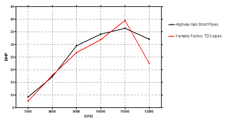
Chart 5. Compares the Highwayman short pipes to the Yamaha Factory TD3 pipes. The factory pipes have an impressive 39 rear wheel HP power peak but with a narrow power band. This difference is highlighted below in Chart 6.
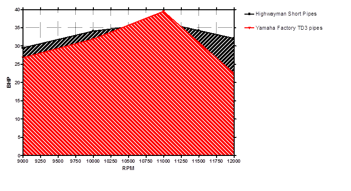
Chart 6. Shows an area under the curve (AUC) analysis comparing the highwayman short pipes to the Yamaha factory TD3 pipes. The highlighted AUC’s compare the total integrated amount of power available across the range of 9000 – 12000 RPMs. The Highwayman Pipes have an AUC of 101300 HP*RPM vs 96050 HP*RPM for the Yamaha Factory pipes. This analysis indicates that the Highwayman pipes have an average of 5.2% more power available across this range with a flatter smoother delivery that will be easier to ride. Unless the track favors nearly constant operation at 11000 RPM the Highwayman Pipes should win.
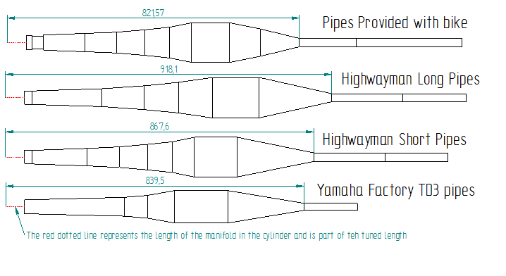
Figure 2. Scale drawings of the pipes tested, showing their tuned lengths.