
The Highwayman F37 a custom, purpose-built vintage road racer, Part I
This story highlights the creation of a road race engine from the fusion of two different enduro motors, as well as the design and fabrication of a custom racing chassis to house the “franken-motor.”
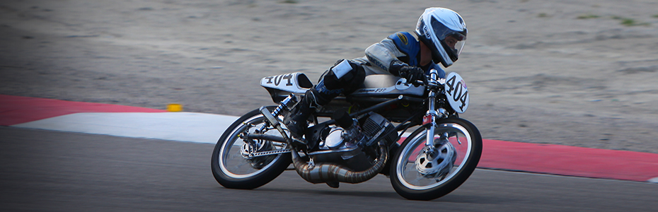
The above video was shot aboard the Highwayman F37, ridden by Jeff Henise, and finishing 3rd in a 2014 AHRMA national race at Barber Motorsports park in Alabama, USA.
Willow springs GP250 2019 – 1st place!
Philip Island AU, Post Classic 250 2019 – 4th place!
Follow the story the home – cast nikasil plated cylinder here.
http://www.alloyavenue.com/vb/showthread.php?11802-Air-cooled-2-cycle-motorcycle-racing-cylinder/page3
The story below (Part I) describes the construction of the Highwayman F37 engine, Part II covers the design and construction of the chassis and expansion chamber.
After riding and building motorcycles for a little over 20 years I finally decided to try my hand in competition. In the summer of 2013 I began road racing with AHRMA (The American Historic Motorcycle Racing Association). I modified a 1968 Yamaha YCS1 180cc two-stroke twin to compete in their GP200 class. Even though it was their smallest road racing class displacement wise, GP200 was one of the most populated classes on the grid with an average of 25 bikes entering each race, so competition was fierce. A majority of the bikes in this class were four stroke Honda twins: CB160, CL175, CB175, SL175, etc. The most competitive Hondas were highly customized having hot cams, oil coolers, modified heads, tuned exhausts, CDI magnetos, and big bore kits with custom pistons taking them to 209 and even 247cc.
Being the certifiable two stroke nut that I am it would just break my heart to race a four stroke, so I began searching for my ultimate two-stroke GP200 machine for the 2014 racing season. The class had a 1968 year cutoff, so I began researching sub-200cc two-stroke machines produced before then. I chose the 1968-1970 Kawasaki F3 Bushwhacker, a 175cc rotary valve single cylinder enduro. The rotary valve motor should have good power potential (AHRMA does not allow reed valves) and be an advantage over a piston port design. However the down side to the F3 Bushwhacker was its wide ratio four speed gear box, and the fact that F3 parts are super hard to find!
AHRMA allows the use of later model parts if they can be justified as “like design,” so to get around the shortcomings of the F3 I filed an official rules and eligibility request to allow the use of the 1968-1970 F3 cylinder and head on an 1971 Kawasaki F7 bottom end for competition in GP200. The Kawasaki F7 was another 175cc rotary valve single cylinder enduro produced from 1971-1975. The case and cylinder porting of the F7 are virtually identical to the earlier F3 , however the F7 had a five speed gear box, better clutch, and importantly: easier to find parts! AHRMA will not allow the F7 outright in GP200 because its production year stared after 1968 cutoff.
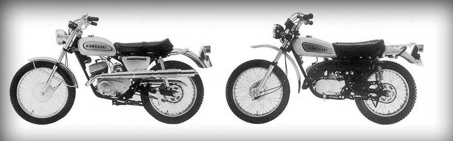 Left: Kawasaki F3 Bushwhacker. Right: Kawasaki F7.
So that is how this adventure began, deciding to mate a Kawasaki F3 cylinder to a Kawasaki F7 bottom end to satisfy AHRMA requirements to compete in GP200, then modify the resulting engine for road racing, and also build a racing chassis from scratch to house the thing. Perfect for a guy who loves to build unusual machines and do things different from the pack.

Now onto the project! I only had 5 months to build this engine and bike before the first race meet. I spent countless hours on the internet researching and mail ordering parts galore. The photo above shows the first F3 cylinder and F7 cases to arrive, old and dirty as most used vintage bike pars show up, but in decent working shape. I noticed right away that even though the transfer ports lined up, the F3 cylinder was NOT a bolt on option, it had a wider stud pattern and lowed deck. This is going to take some work.
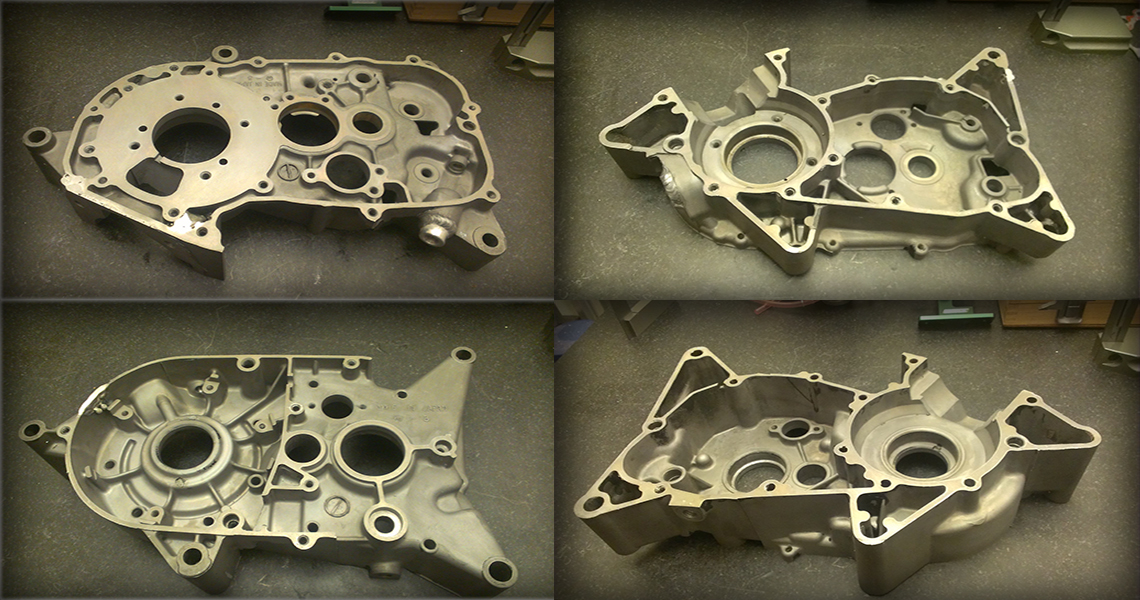
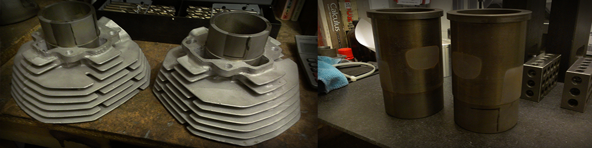
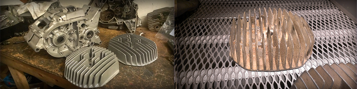 Right: F3 head before bead blasting. Left: Cleaned up heads and cases after bead blasting.
First things first. The major engine components are degreased and cleaned by bead blasting. Then the cases are prepped for welding to relocate the cylinder studs, widen the cylinder deck, add a threaded bung for a breather tube, and block off an unneeded check valve hole.
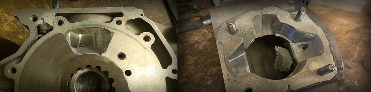
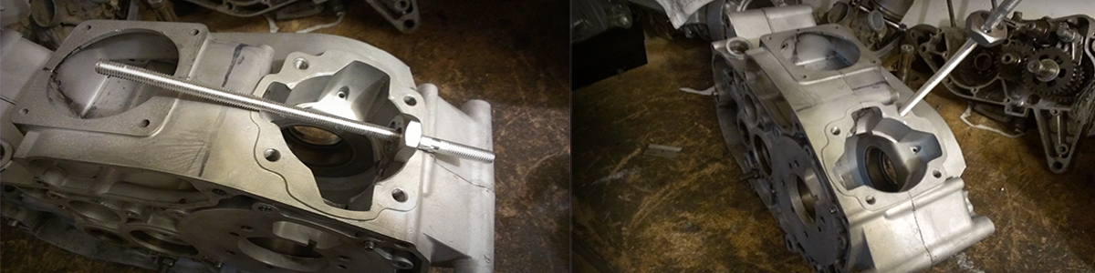 An aluminum rod is threaded then screwed tightly into the existing stud holes then cut off near the deck.
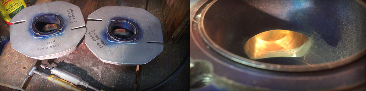
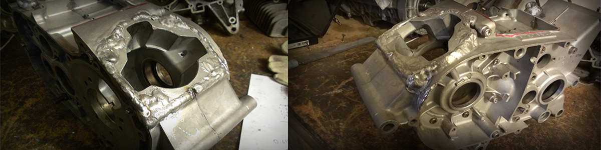 Here is the deck after welding. The weld is allowed to penetrate the threaded inserts and seal off the old stud holes. Al lot of material needed to be added to the left side to support the wide F3 cylinder base.
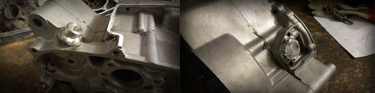 Left: threaded vent bung added. Right: plug welded in to block off a check valve hole.
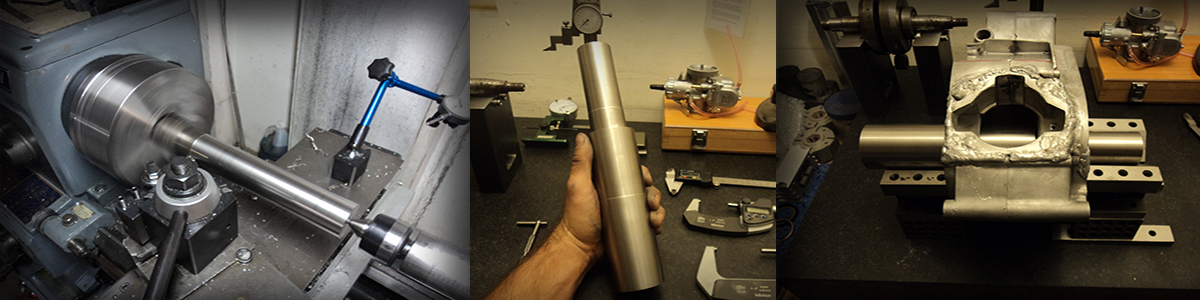
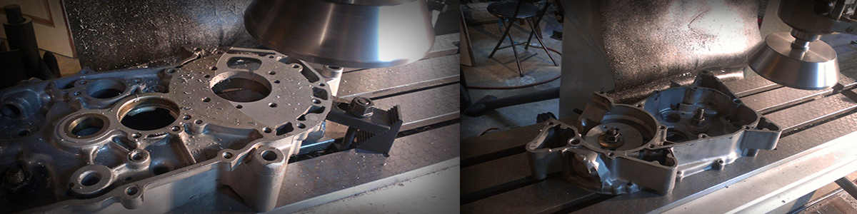
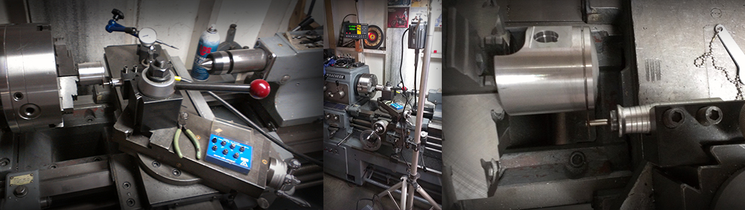
Next the lathe is fired up to machine a steel mandrel that tightly fits the crankshaft bearing housings in the crank case. This mandrel will be used to align the cases on the milling machine in order to machine the cylinder deck.
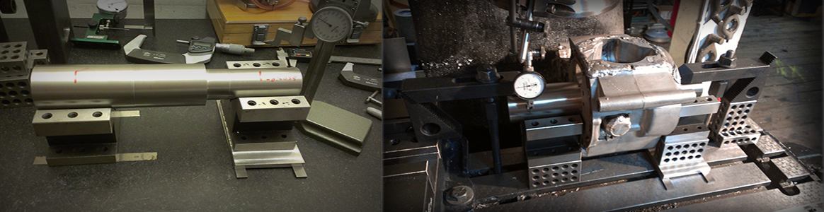 Left: Finding shims to hold the case mandrel level. Right: aligning the cases to the mill with the mandrel.
Here is my homemade cast iron fly cutter in action leveling the cylinder deck.
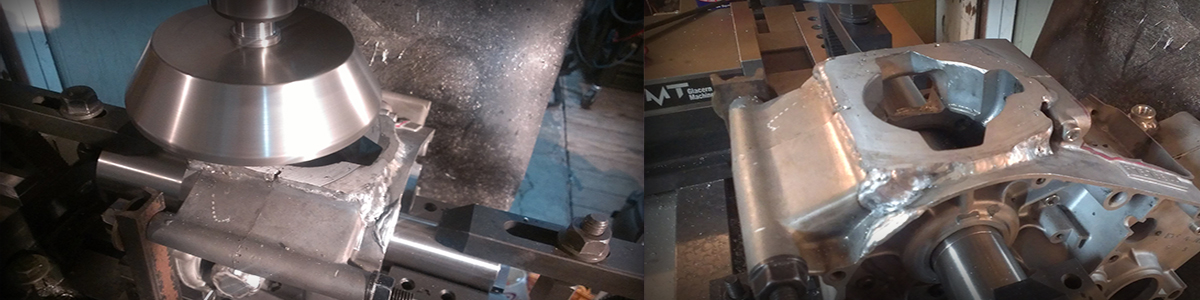
Video: Fly cutting of cylinder deck on freshly welded cases, roughing pass.
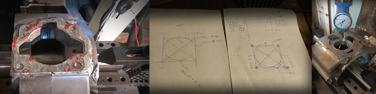
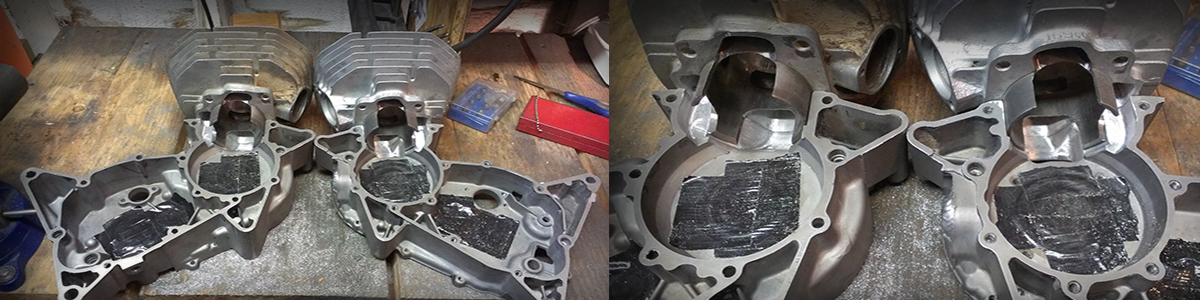
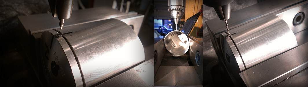
Now that the deck is flat the stud holes will need to be drilled and taped. The above image shows a gasket matched to the F3 cylinder aliged with the transfer passages in the cases, a drawing of the bolt hole layout, and a centering ring used to center the mill spindle to the case bore.
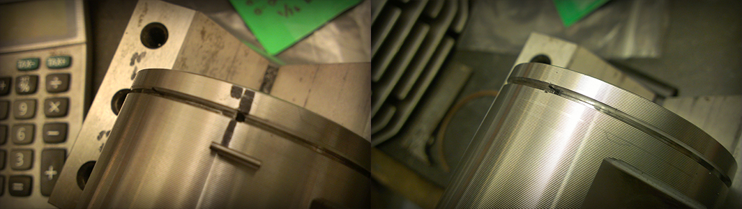
 Left: finished cylinder deck, machined level and new bolt holes drilled and taped. Right: An F3 cylinder sits on F7 cases for the first time ready to bolt. The F37 is born!
The four gasket faces including the rotary valve face are all skimmed flat with the fly cutter to correct for warping from welding. This means that the shimming on the crankshaft and transmission change-drum will need to be altered too as the cases are about 0.02” narrower then stock.
Video: Fly cutting of engine case rotary valve and gasket faces to flatten after welding, finishing pass.
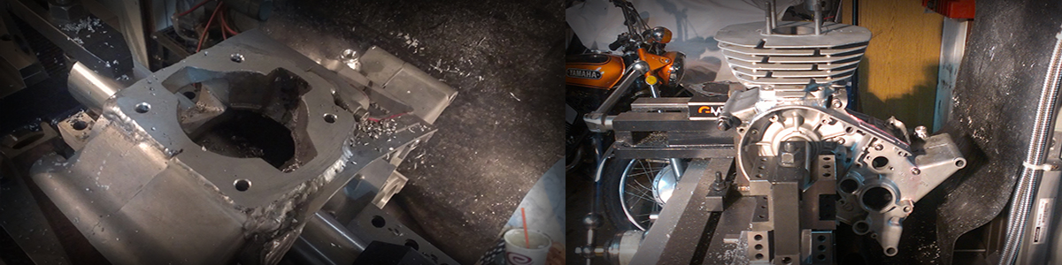
The finished F37 cases with: Relocated cylinder studs, removed air box housing, and fly cut gasket surfaces.
Next some port work is done to cases to enlarge and match the intake port to the rotary valve, and the transfer passages to the cylinders. A special disk valve is cut for the desired intake port timing.
The image below shows the port work on the transfer passages to match the cases to the cylinders.
Now on to the cylinders!! Brace yourself. After much study I realized that the stock cylinders liners just wouldn’t do. Mainly because I wanted to run a lightweight forged piston that would withstand the high piston speeds (> 4000 ft/s) that this motor would generate with its rather long stroke. The best candidate piston available from Wiseco had a compression height that would require reworking of the cylinder port heights, adjusting the deck height, and adding a longer cylinder liner skirt to keep the piston from dropping out of the bottom of the cylinder at BDC.
To fix these cylinder issues I had to:
1) Completely remove the stock cast iron liners.
2) Weld the exhaust and transfer ports to a lower height.
3) Make iron liners with new specs from scratch.
4) Re-port the liners and cylinders to match.
Some say that if your ports are too large or too high that the cylinder is useless, and that in porting you can only grind metal away and can never be put back. I am about to prove that metal can be added and that ports can be made lower and smaller (if needed), it is just a lot of work!
I really need to thank John Tice from Small Engine Machine Works in Oregon for the invaluable information he shared with me from his 30+ years of experience making custom sleeves for two stroke cylinders. I owe the good results in this endeavor to him! John learned from his father and between the two of them and their shop they have over 100 years of combined experience sleeving two stroke cylinders. I feel very fortunate to have been able to absorb mush of John’s knowledge on the subject.
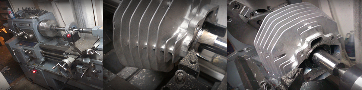
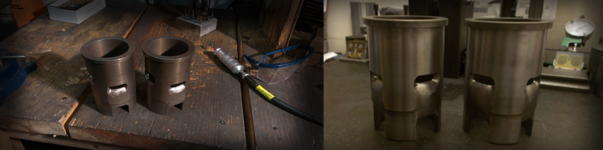
First the cylinder is held on an expanding mandrel in the lathe and the cast iron liner skirt is cut off.
Next the cylinder is centered on the mill, and the liner is bored out. Right: Notice how ribs of iron remain in the aluminum, in many Japanese cylinders of the era, the iron liner is ribbed on the outside and actually cast into the aluminum. It takes extra boring to get down to pure aluminum (below).
 This image (above) shows a cylinder after all of the iron liner has been bored away.
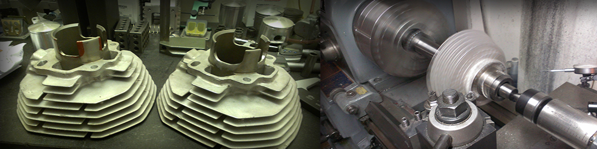
After the iron liners are bored away metal is added to the ports by TIG welding (below) to lower their height, also the entire exhaust passage is made narrower. These old cylinders tend to have too wide of a taper in the exhaust port and need to be streamlined to increase exhaust port velocity for better performance.
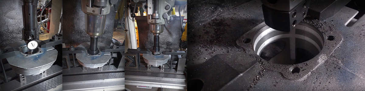
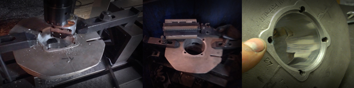 Above Left: Milling off the excess weld in the bore, and cutting a flange in the upper deck for the new liner. Middle: precision honing of the bore to remove taper and out-of-round, create a solid bearing surface to hold the new liner and have good heat transfer. Right: Honed cylinder showing the flange that was cut into the upper deck.
The above panel (Left) shows scribes lines to indicate the port window widths and heights, and port windows cut close to final size (right) by hand after several hours at the porting bench.
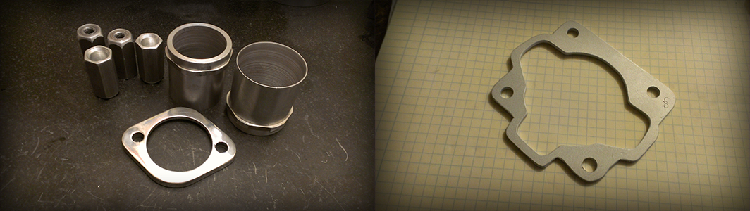
Next a cylinder liner is fabricated from a centrifugally cast moly-iron casting. The above image shows this casting and a cut chunk that will be made into the cylinder liner.
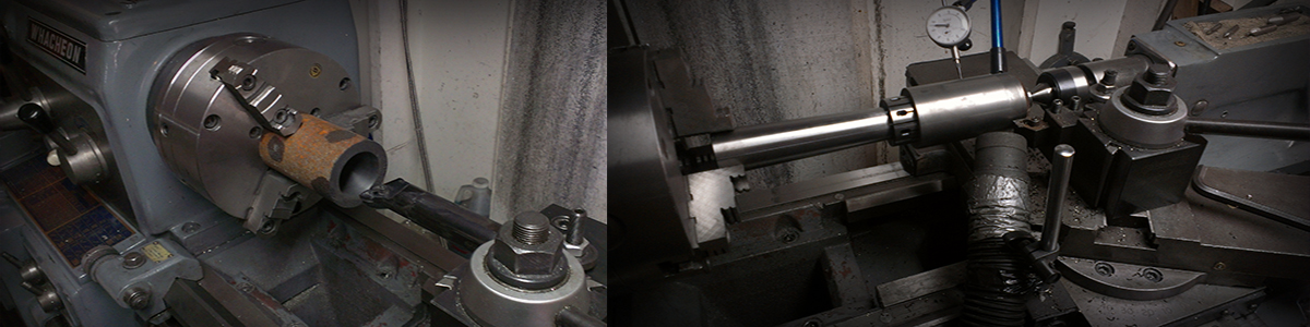 The crude liner is bored on a lathe to around 0.010” under the final size (above left), then holding the bore in an expanding mandrel the exterior features are machined. The outside of the liner is machined to its final size, exactly 0.005” larger than the honed cylinder that it will be installed into. That’s right the liner is actually larger than the aluminum cylinder housing, and needs to be installed by a thermal interference-fit process, it can not be pressed in.
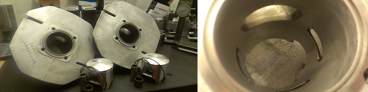
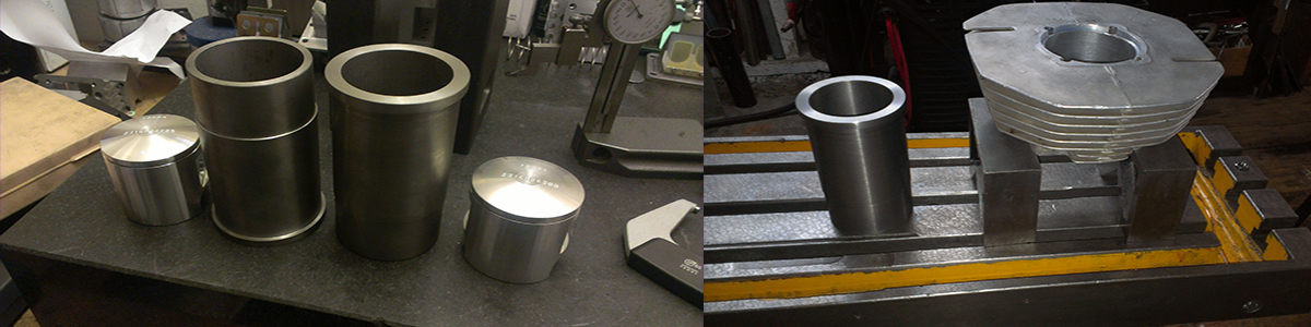 Left: Finished liner blanks (without port windows) next to the pistons that will run in them. Right: A liner blank ready to install into a cylinder housing.
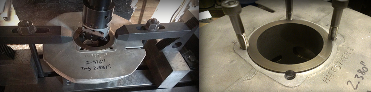
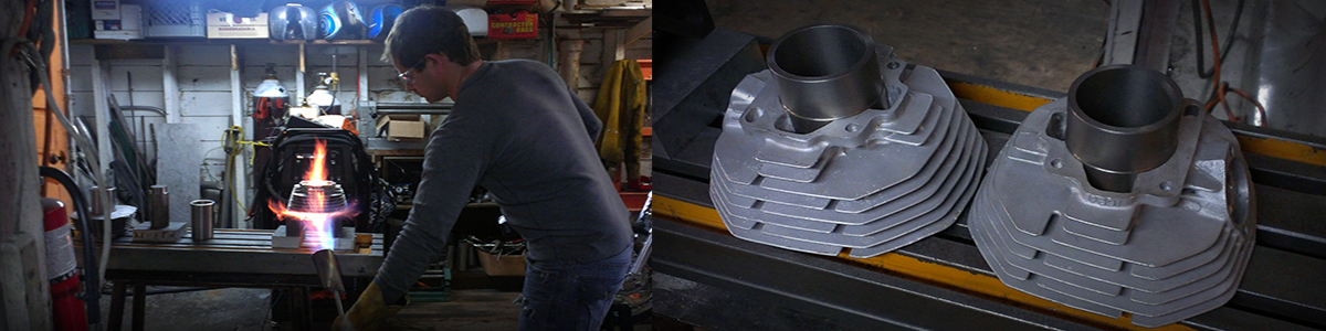 Left: heating an aluminum cylinder housing to expand the bore. Right: Iron liners installed into the housings.
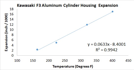
Next the cylinder housing is heated (image above) to expand the bore so the liner can be installed. Remember the outside of the liner is 0.005” wider in diameter than the bore of the cylinder housing. If you are wondering how much the housing has to be heated look at the chart below. I plotted the cylinder housing bore diameter vs. its temperature and determined the bore’s coefficient of expansion by linear regression. The aluminum bore expands 0.000063 in/oF. This means that if you heat the cylinder housing to 400 oF the bore will expand 0.025” in diameter (over half a millimeter!) and the liner drops right in, no sweat!
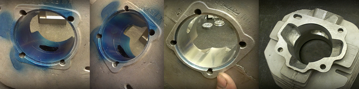
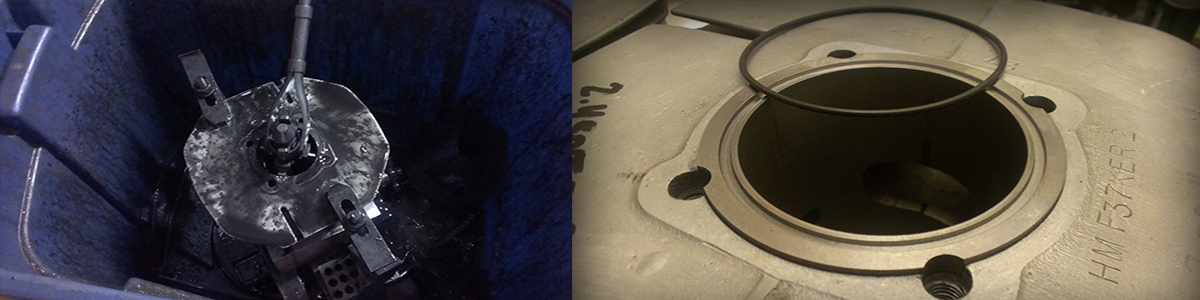
 Above: The port windows are etched onto the liners by bead blasting then the cylinders are heated as above to drop the liners out.
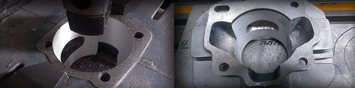
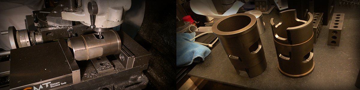 Above: A milling machine is used to cut the port windows to near final size. The final porting will be done by hand after the liners are back in the cylinder housings.
 Above: After milling the port windows the transfer passage walls are streamlined by hand at the porting bench.
 Above: After the liners are reinstalled into the cylinders, more shaping of the transfer windows is done by hand to match the cases, and the decks are cut flat on the lathe.
 Above: The liners are reinstalled into the cylinders, the bores are bored to near final size, and the head stud holes are counter bored to accept the head bolts (right).
 Above: Precision honing is used to get the final bore diameter and proper bearing surface for piston ring seal. An O-ring groove is cut into the upper deck for use as a head gasket.
 Above: Back at the porting bench, the port windows are accurately cut to their final size, and the port passages are streamlined.
 Above: After a quick finish hone and clean up, the twin Highwayman F37 Cylinders are ready to run!
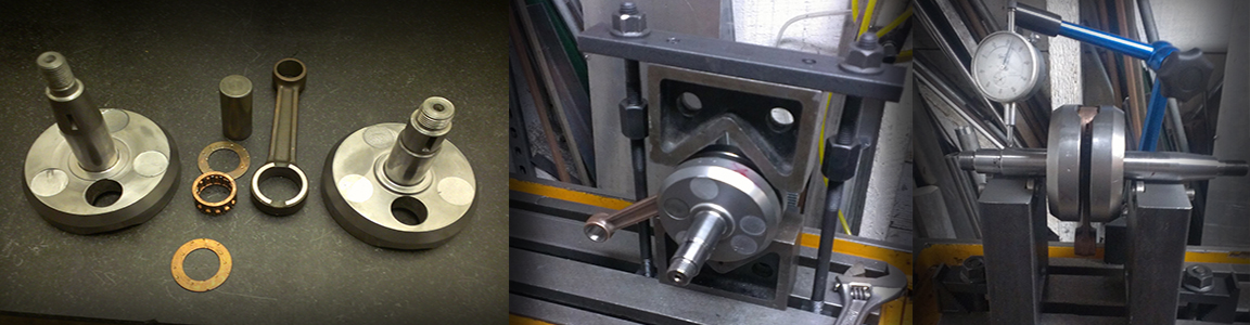
Next a crankshaft is built, stock webs, pin, rod, and bearings are used. All parts are new except the webs and spindles, however spindles are selected with no rust pitting where they must seal against the case seals. Air leaks can be the death of a two stroke! The right two photos (Above) shows my homemade crank truing fixtures: one for raping (Above, Center) into alignment, and one for measuring runout (Above, Right). Both fixtures are attached to an old milling machine table. The fixture for measuring runout can also be use for measuring the balance factor. Care is taken to get the crankshaft’s runout to <0.001” in any dimension. Runout comes from two sources: 1) the webs being misaligned about the axis of the pin, or 2) the webs being misaligned perpendicular to the axis of the pin. When measuring runout with the dial gauge they generally show up with the high/low spot being 90 degrees or 180 degrees to the big end pin respectively. After some practice it is easy to spot the source of the runout and know how to rap the webs into alignment.
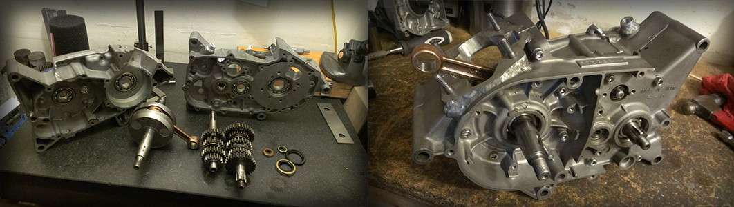 Above. Transmission components are stock, with a few gear swaps to get a closer ratio 4th – 5th. Bearings are fitted into the cases (I use top quality SKF bearings) by heating the cases to ~200 oF in an oven so the bearings just drop in. With crank, cases, and tranny in hand, the bottom end is assembled!
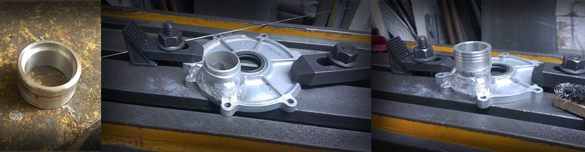 Next the rotary valve cover is modified to accommodate a larger spigot-mount carburetor. The spigot is machined on the lathe (Above left), the stock rotary valve cover is built up with weld in the areas where is will be widened by porting (Above Center), and finally the spigot is welded to the modified cover.
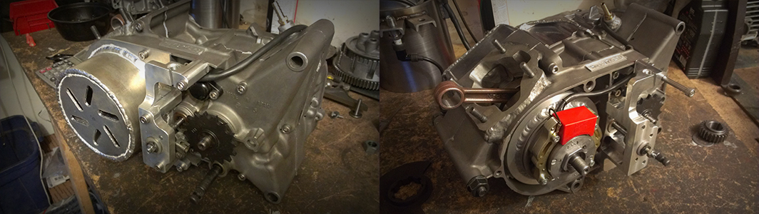
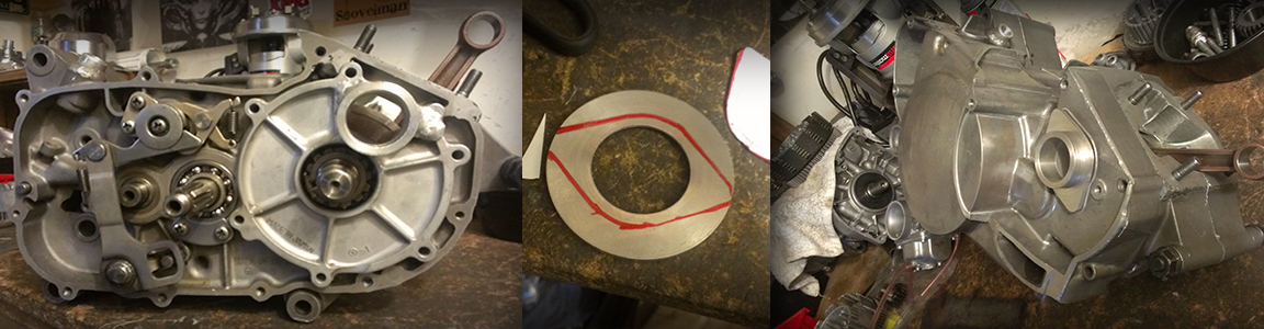 The photos above shows the modified intake cover on the bottom end. Note the nice streamlined straight-shot intake tract. A plate was fabricated that retains an O-ring against the clutch cover (Above, Right) to keep the gear box oil in.
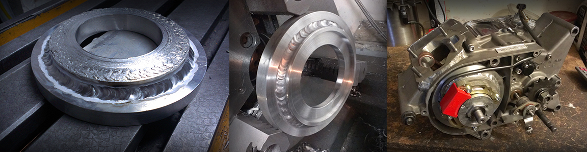 An ignition backing plate (Above) is made from billet aluminum. I didn’t have a big enough single piece on hand so two were welded together. The low inertia magneto-CDI ignition electronics are by Horse Power Ignition (HPI).
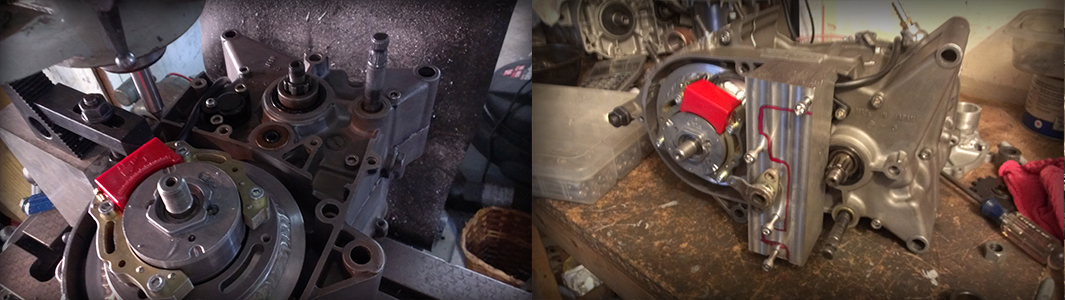 Above. Making a heavy duty clutch release. (Left) the engine is mounted on the milling machine and a center finder is used to locate the bolt holes for the clutch release, their coordinates are mapped using the digital readout (DRO) on the mill. (Right) shows a billet that will be used to make the clutch release with bolt holes drilled from the DRO hole map, they fit perfectly
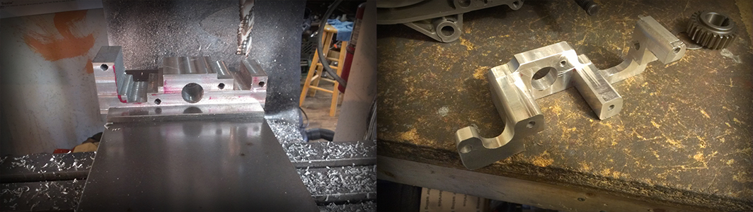 Above. After a bunch of milling work (left). The clutch release mount exists (right).
 Above. Shows the custom heavy duty clutch release mounted on the engine.
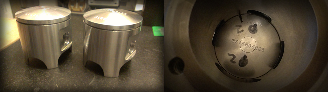
These projects seem to never end! In order to run these lightweight, single ring, forged Wiseco pistons (Above) the ring pin will need to be relocated to keep the end gap out of the rear transfer port. The ring will be pinned to the position noted in the upper right image.
 Above. A tool post grinding set up is used on the lathe with a thin cutoff wheel to grind the old ring pin out of the piston. A DRO is used to slowly move the cutoff wheel ~0.0002” at a time to carefully grind out the pin without scratching the 1 mm wide ring groove.
 Above. The hole for the new ring pin is carefully drilled on the mill, note the forging bump under the piston crown where the new ring pin hole is being drilled (center).
 Above. The new ring pin (left), and the new ring pin pressed in (right).
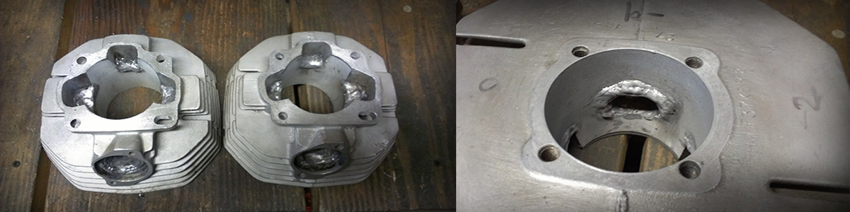
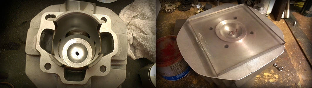
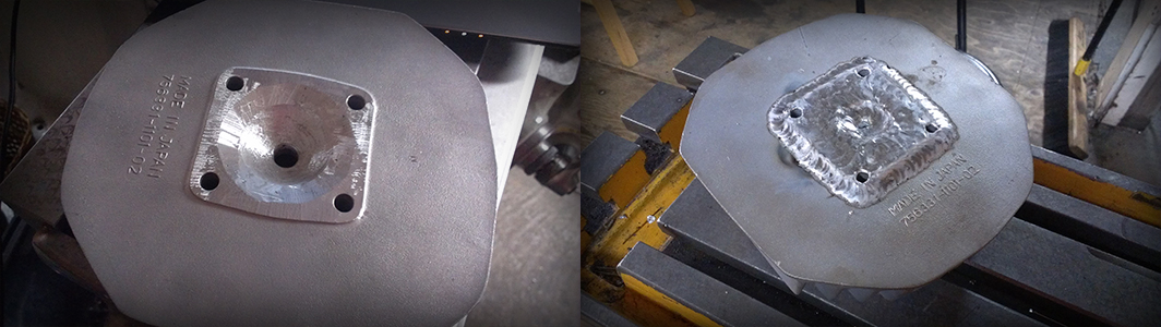 Above. Every great engine needs a great cylinder head. The stock combustion chamber is ground clean then filled in with weld, note the thick extra material added to the deck.
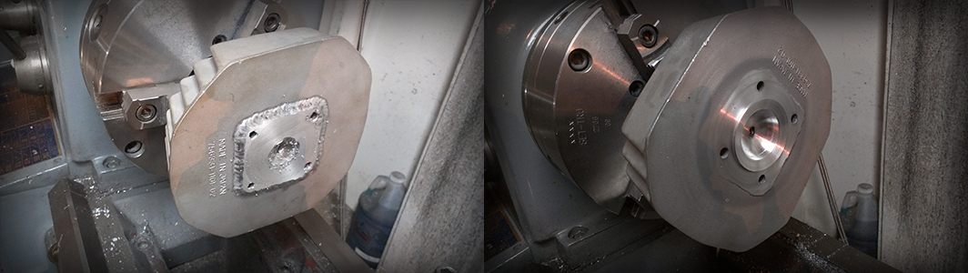 Above. The new combustion chamber is turned on the lathe. Note this is a “drop-in” design, meaning the combustion chamber actually drops into the top of the cylinder to center.
 Above. The drop-in combustion chamber in the cylinder (left). Checking the combustion chamber volume by alcohol titration (right).
 Above. Custom head bolts are made (left), and a base spacer to get the port timing right (right). Now the engine can be assembled (below)!!
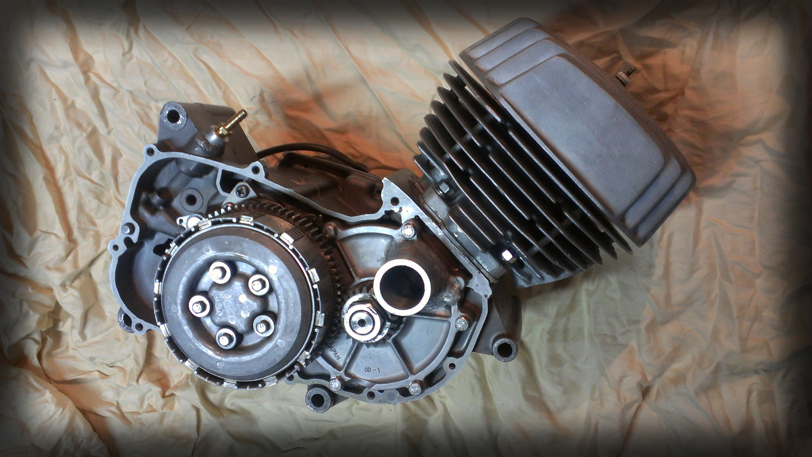
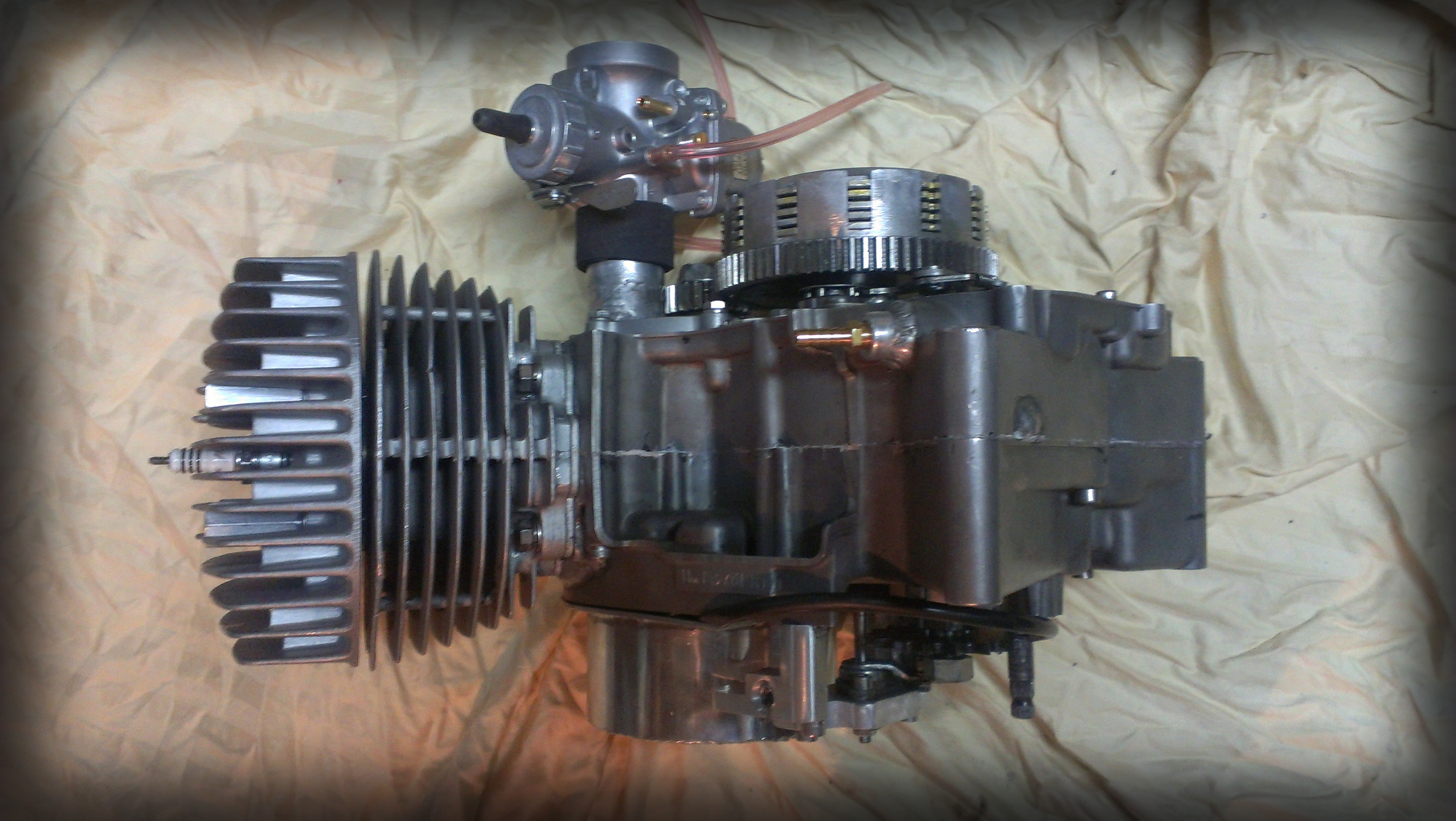
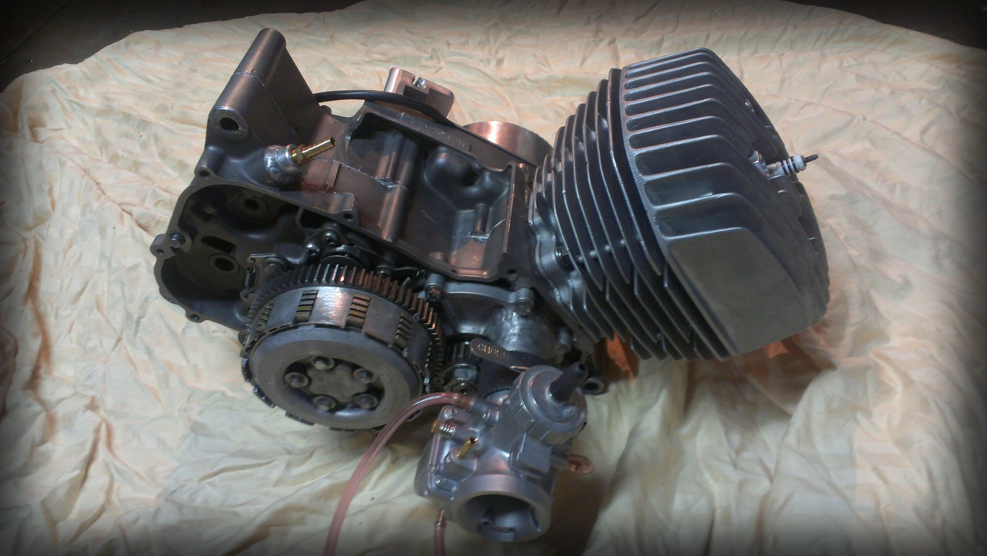 The Highwayman F37 engine, with 6-plate clutch.