
Design and construction of The Highwayman F37 road racing chassis, Part II
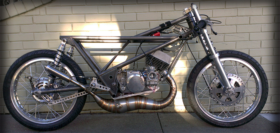
This is Part II of the F37 story that covers the design and fabrication of the thin wall chromoly road racing chassis. Construction of the engine and some racing footage aboard the finished bike can be found here in Part I.
The design of this racing chassis was inspired by my friend and chassis builder Michael Moore (eurospares) who has provided countless hours of discourse and discussion on the theories of racing motorcycle design, metal fabrication, and manufacturing technology in general. A majority of all my ideas are ran past Michael at some point! Michael steered me towards the works of John Bradley author of The Racing Motorcycle: A Technical Guide for Constructors, Volume 1 (1996) and Tony Foale, a brilliant engineer, and author of the book Motorcycle Handling and Chassis Design: the art and science (2006). It was the ideas from these books and Michael’s consultation that ultimately lead me to the design of the F37 racing chassis.
The style of the F37 chassis was inspired by the Colin Seeley MK3/MK4 chassis and Michael Moore’s Honda CR216. The unique mono-shock front end was inspired by the 1965 Dawson’s Motors Wolverhampton (DMW) Typhoon Grand Prix racer (below). However the inspiration stops there, the design of the engine, expansion chamber, choice of components, and frame geometry (rake, trail, wheel base, height, center of gravity, rider position, etc) are a Highwayman concoction by Jeff Henise.
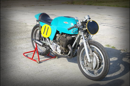
1965 DMW Typhoon, inspiration for the mono shock front end on the Highwayman F37.
The beginning of the design started by selecting the wheel base, trail, and center of gravity. The wheel base and trail were selected by studying specs from modern GP bikes and comparing those to known AHRMA GP200 bikes with riding experience, the result was something similar to a Honda RS250.
Designing the center of gravity is a little more complicated. To actually calculate the center of gravity would require knowing the center of gravity of every component of the bike and the rider in gear. Of course this is impossible if the bike doesn’t exist but estimates can be made by making measurements of similar parts.
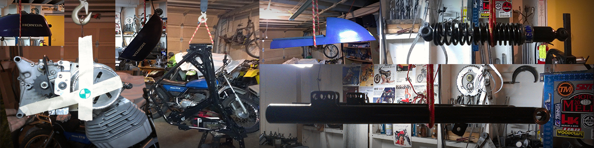
The center of gravity of individual parts is determined by hanging each part from two locations, where the two vertical axis cross is the center of gravity for that part (see engine, left).
Deciding where the center of gravity should be is done by comparison to the center of gravity of an existing race bike that you know the feel of, in this case The Highwayman YCS1.

The same part-hanging technique can be applied to an entire bike to determine its center of gravity.
Now we can begin predicting where we want the center of gravity (CoG) of the new design to be. Since the wheel base, rake, and trail are chosen: the wheels, forks, and triple clamp offset can be drawn to scale. Next we model the rider position with a little help from “Fred.” The rider model, Fred, can be scaled to the rider’s size, manipulated into the riding position, then by summing the products of the body part’s weight contribution with their horizontal and vertical positions and dividing that by the total weight the center of gravity of the rider can be determined. This is less complicated then it sounds, hopefully the following drawings will make it makes sense.
Horzontal position of CoG = (Wx1 +Wx2 + Wx3 + …)/total weight
Where Wx = weight x horizontal position of a part
Vertical position of CoG = (Wy1 + Wy2 +Wy3 + …)/total weight
Where Wy = weight x vertical position of a part
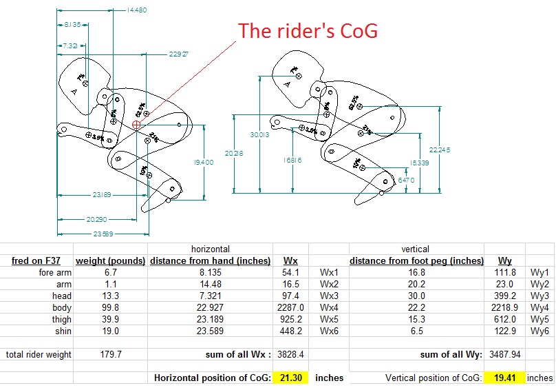
Using a “Fred” rider model to predict the rider’s center of gravity (Cog). note: The percentages on Fred’s body parts indicate the contribution of that part to Fred’s total weight.
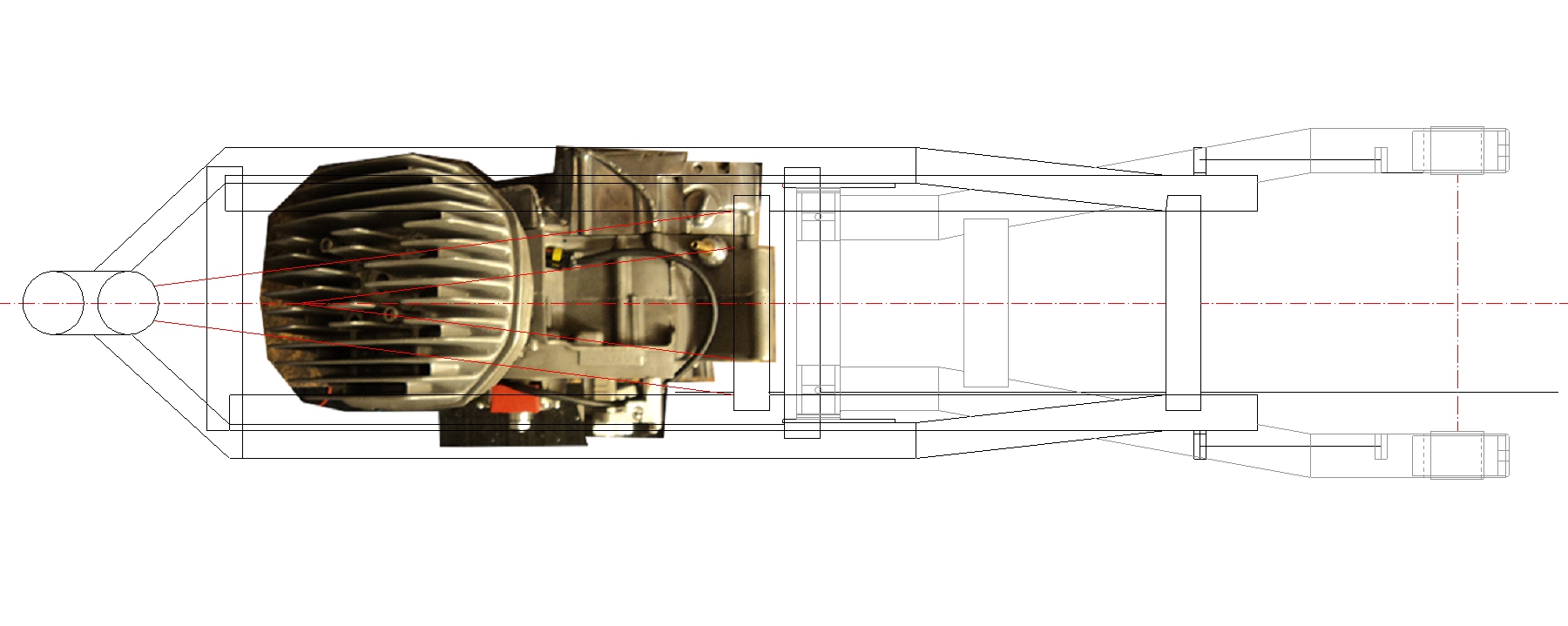
OK, as mentioned earlier the wheels, forks, and triple clamp offset can be drawn to scale based on the chosen specs. Now Fred can be added to the drawing, this begins to determine the seat height, foot peg position, and the location of major parts like the gas tank and seat. We then start to mess with the engine position to tune the center of gravity to our desired location. These small bikes with light engines tend to be rear wheel heavy, and in the case of the F37 the engine was shoved way forward to attempt to weight the front wheel to ~50% of the total bike+rider weight. We apply the exact same analysis that we did to Fred’s parts to all the bike’s parts (including Fred, the rider is part of the bike!) to determine the location of the over all CoG.
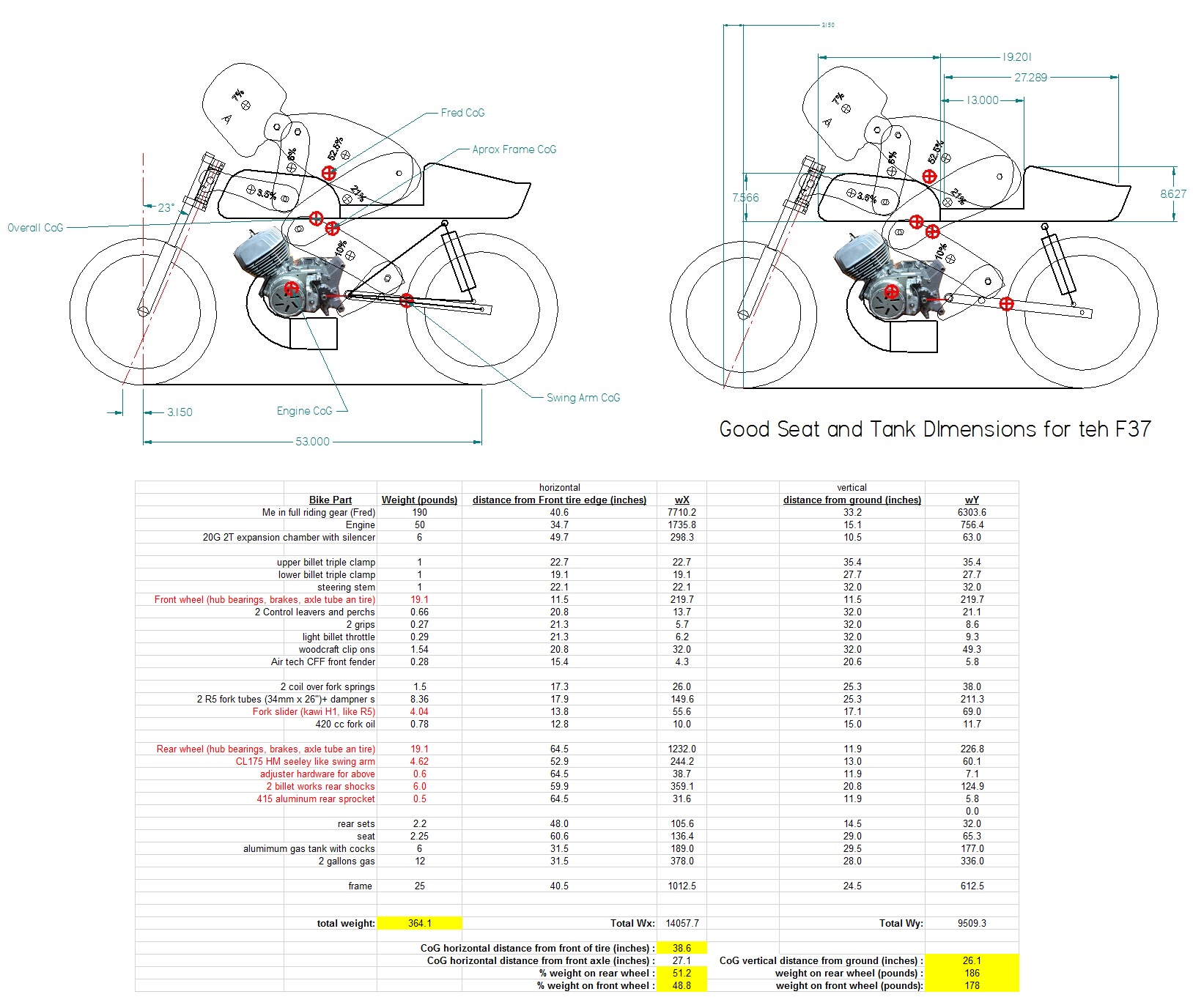
Center of gravity (CoG) prediction for the F37 design including the rider (Above). The vertical position of the CoG effects the handling: lower = easier to “flick around” with less traction, Higher = less responsive handling with more traction (think of how endure riders stand up for stability). The horizontal position of the (CoG) effects the steering characteristics and traction on each wheel, modern race bikes will have 45-60% of the weight on the front wheel. It is hard to get 50% of the total weight on the front wheel with a small vintage bike, as a result the engine in the F37 is very far forward and the drive chain and swing arm are very long to get ~49% of the weight (bike+rider) on the front. After studying racing photos of the F37, the ridre position is still often far forward in corners to further weight the front end.
At this point the location of all the critical components are known: Rider, Engine, Wheels, Forks. Based on the known fork position the triple clamps can be designed to give the desired trail, this also locates the position of the head tube, then the swing arm location can be chosen. The critical things to consider in choosing swing arm location are: 1) will the chain clear the pivot tube with the required sprockets? 2) what will the squat/anti-squat characteristics of the swing arm geometry be? For the F37 a geometry was chosen that offers chain clearance, and provides some degree of anti-squat (the rear wheel is forced into the ground for traction under acceleration force) at all possible suspension compression levels. The image below shows these components in various states of suspension compression, the trail as a function of compression (to make sure an “extreme” condition is not created), and the ground clearance can also be predicted here as a sanity check. The upper pivot position for the rear shocks was chosen to give equal lengths between the swing arm pivot and upper and lower shock pivots, this geometry provides maximum rising-rate during compression.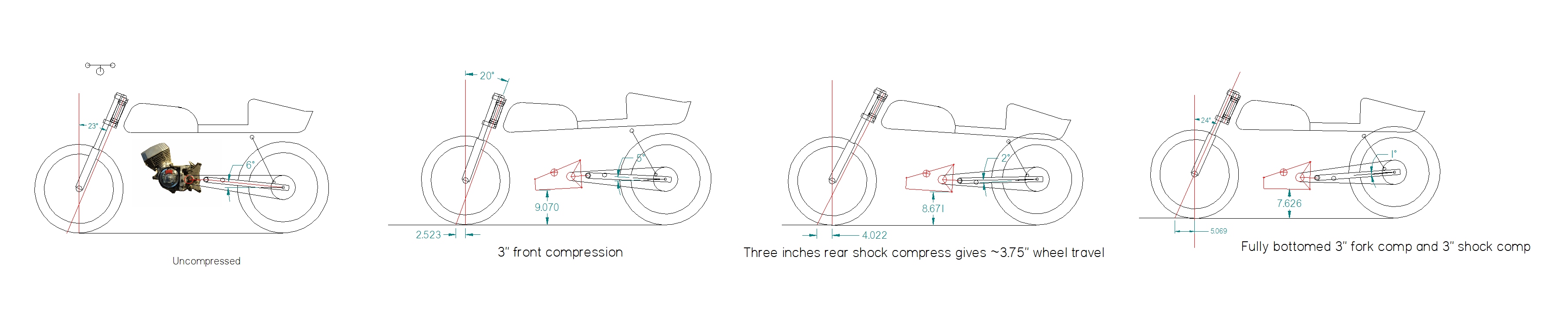
Analysis of trail, chain clearance, squat characteristics, and vertical ground clearance as a function of suspension compression.
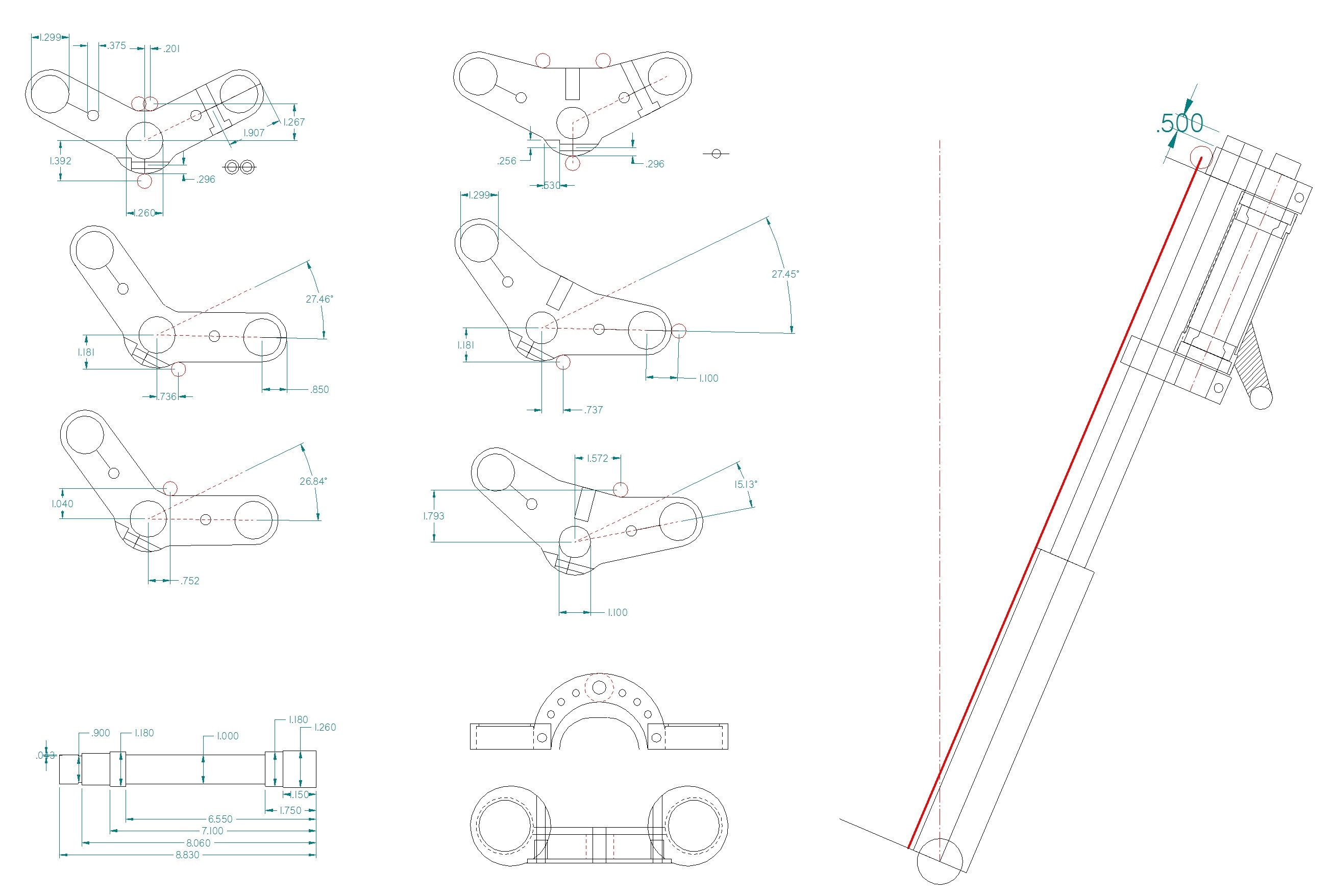
Design of the F37 mono-shock front end showing upper and lower triple clamps (the upper shock pivot will attach to the upper triple clamp), the fork-brace that also functions as the lower shock pivot, and the modified 1968 Honda CB350 forks (no internal springs or dampening mechanism) that will be used for support.
Now that everything is in place, tubes can be designed to hold all the components where you want them, aiming to make a rigid connection between the head tube and swing arm pivot. No cradle will be used, the structure is on the top side of the motor only, and small “dangler” tube is used to support the front of the engine. For this frame thin wall 4130 chromoly tube will be used. Many frames are constructed from 1” OD tube of ~0.07” wall thickness. By using 1.125” OD tube of wall 0.049” any given tube will be ~124% stiffer and 4% lighter than the same tube made with thicker wall 1” OD standard. Because this thin tube does not bend easy no bends will be used in the frame’s construction, all tubes are straight sections with mitered joints.
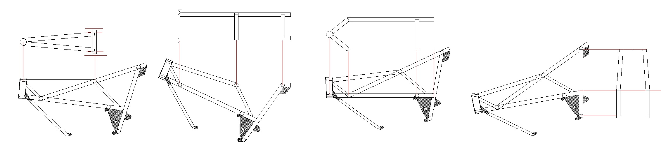
Here is the design for the thin wall chromoly frame tubes. Tube stiffness comes more from diameter than wall thickness, so 1.125″ OD x 0.049″ wall tube was used, this tube is 124% stiffer and 4% lighter than common 1″ OD thicker wall tubes used in frame construction.
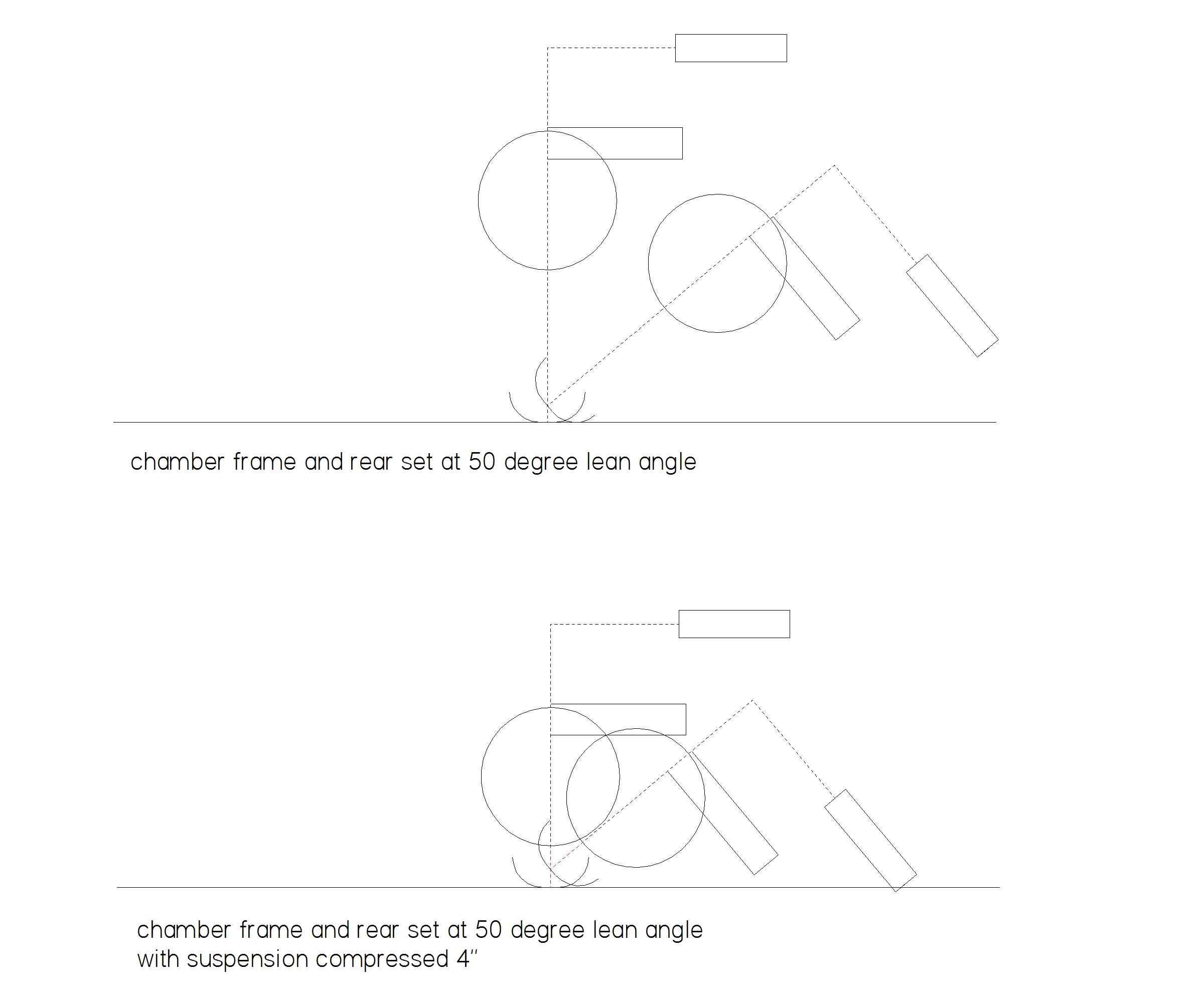
And finally the design is checked for ground clearance at a 50 degree lean angle under full suspension compression.
Next you must get busy in the shop and make it happen!
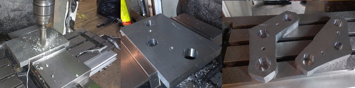
Boring of critical holes for the stem and forks then roughing out the triple clamp profile…
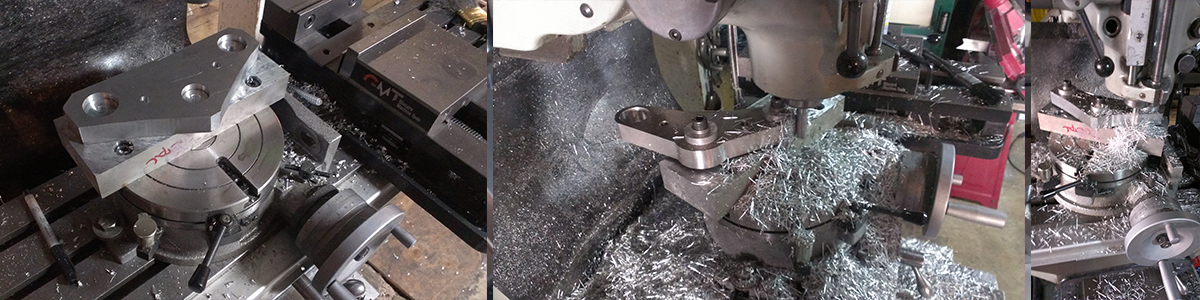
Machining the triple clamp profile. These Triple clamps are made from “Fortal” aluminum, a very strong 7000 series alloy used in mold making, the metal has a nice appearance.
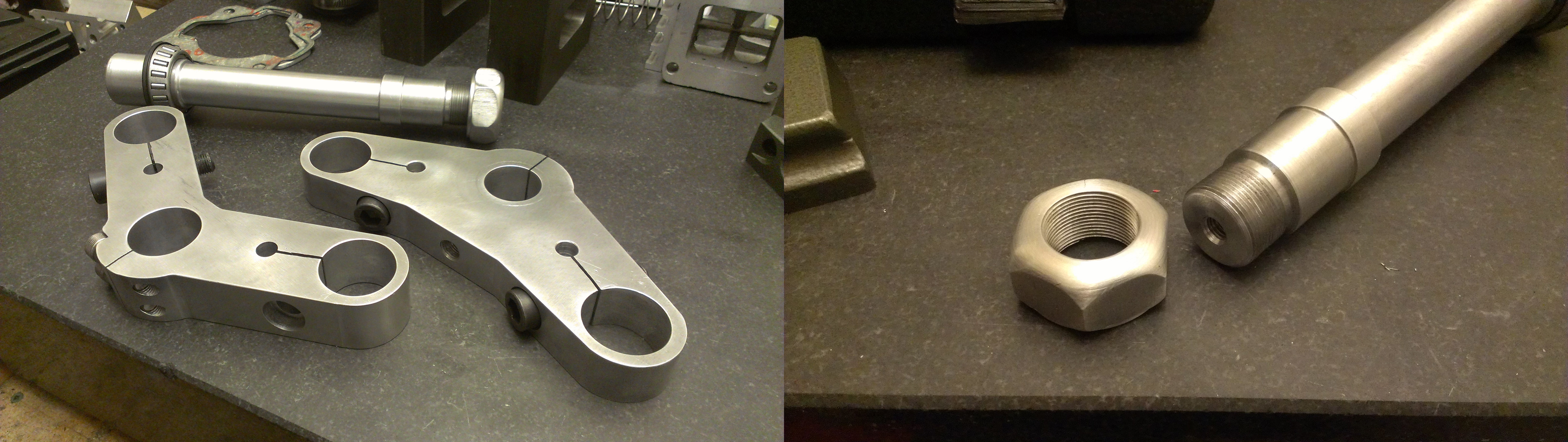
Then after several other operations and some lathe work the homemade triples, stem, and stem nut are in hand!
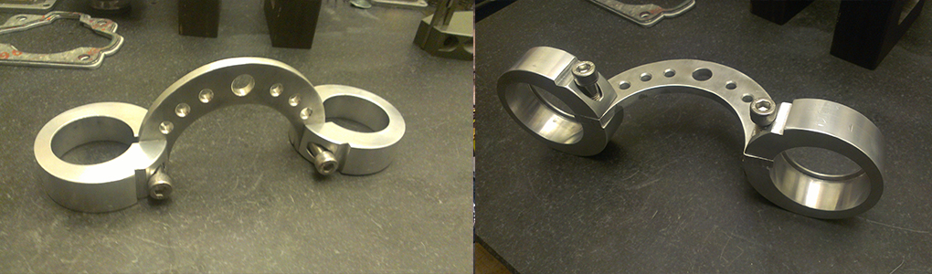
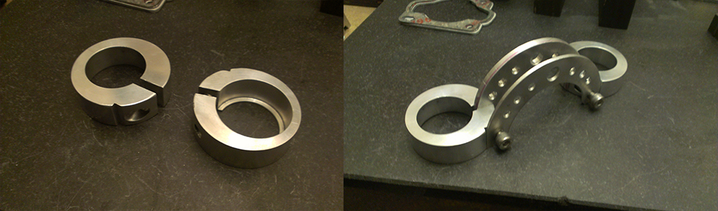
And after more machine work, the lower fork-brace / shock pivot exists…
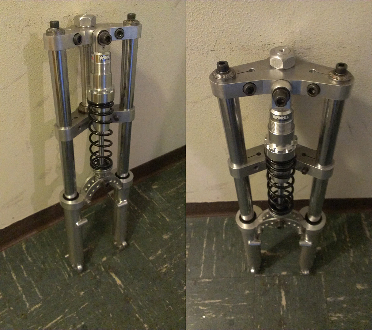
The finished F37 front end. The mono-shock is the only spring and damper and was designed and built specifically for this bike and weight distribution by Works Performance Shocks here in California, thanks Pierre!
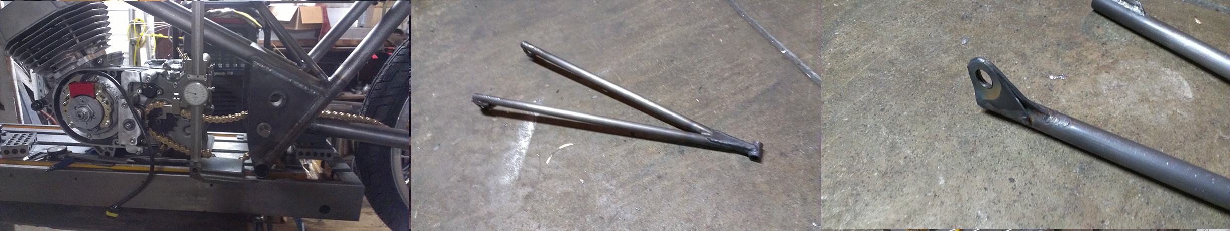
Here is my swing arm hardware inspired by Ducati and Colin Seeley…
Above left: set up that I use on the lathe to cope tube joints. Above Right: swing arm parts.
Fixture used to weld up swing arms, my welding table is an old milling machine table, useful for many other things too, like truing crankshafts.
Here is the finished swing arm with a couple bits of aluminum set-up fixture still attached.
Onto the frame! Above left shows a fixture that will be used to align the head tube during construction, the center image shows the head tube with bearing cups bolted to the fixture, Right shows the bearing cups welded on.
I begin welding the frame tubes together, using my old mill table as a fixture…
More fixturing and welding…
And more fixturing and welding…
Some sanity checks with the height gauge, and the “dangler” that will hold the front of the engine…