Rebuild of a single cylinder press-pin crankshaft – How I do it.
A step by step explanation of how I rebuild simple crankshafts. -Jeff Henise
The rebuild in this article is for two 1974 Yamaha DT175 crankshafts, however the same type of cranks are used in virtually all current production (2017) 2-stroke single cylinder motorcycles and nearly all two strokes produced before 2017. So the techniques shown here can be used to rebuild your state of the art KTM. Multi cylinder press-pin crankshafts can be rebuild with these techniques as well, I have rebuilt twins and triples. Once you acquire the skill you can do a single cylinder crank in about 2 hours, but don’t be supersized if it takes all day your first time.
So lets get started…
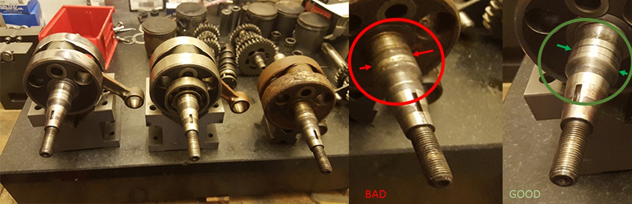
In the image above (left), the two crankshafts on the left are in good shape and the one on the right has problematic rust pitting where the case seal rides. Rust in the seal areas is the main thing I lookout for in an old crankshaft. Too much rust pitting in the seal area, and the case seals will never seal up well, and that is never good for best performance. If it’s an expensive or rare crankshaft with pitting there are ways to repair the shaft, the simplest being thin metal selves (Redi-sleve, Timken; or Speedi-sleve, SKF). Another repair example involves machine-grinding the seal area to a smaller OD and sourcing a smaller seal, and there are others, but if it is cheap and easy to find a good used crank, just get a good one to start with. The close up images above compare the rusted crank to a good crank. On the good crank you can see two smooth polished stripes where the case seal rides, this is normal and how a good used crank looks. Other than that make sure there are no gouges in the shafts, stripped threads, damaged key ways, or other signs of bad mechanical damage. Minor mechanical damage or rust on the webs is usually of no concern, the rust can be removed by bead blasting or similar mechanical process.
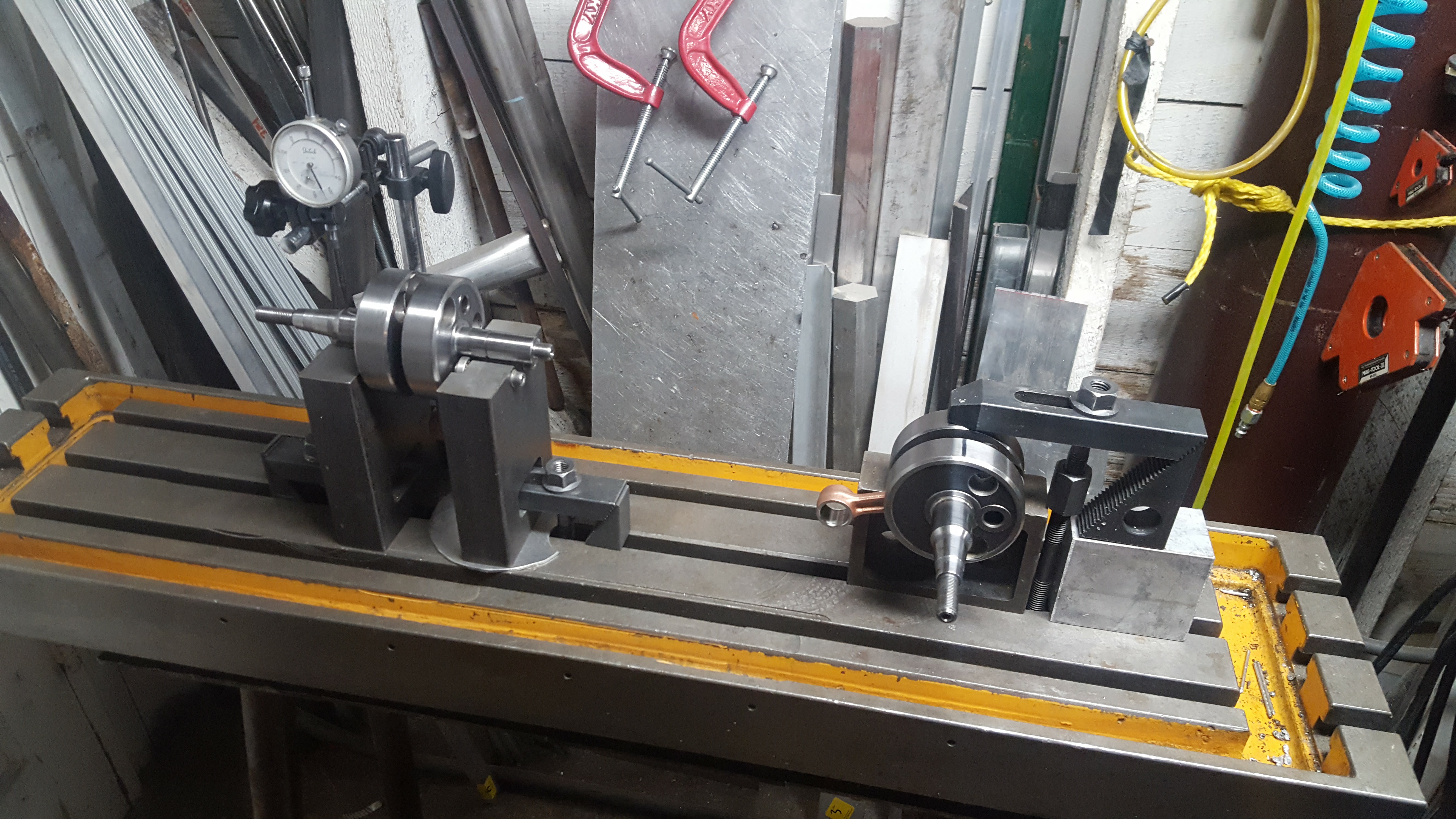
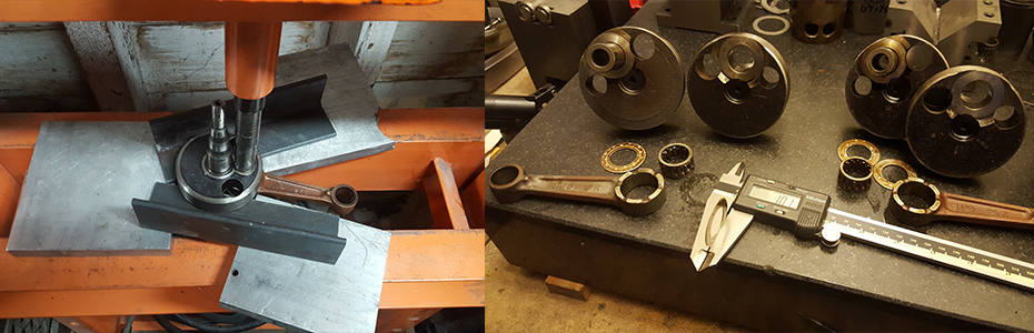
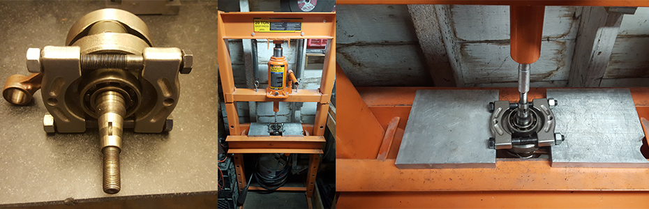 Photo 2. LEFT: Bearing separator used for removal of main bearings. MIDDLE: simple hydraulic press. RIGHT: close up of the press used to remove the bearing.
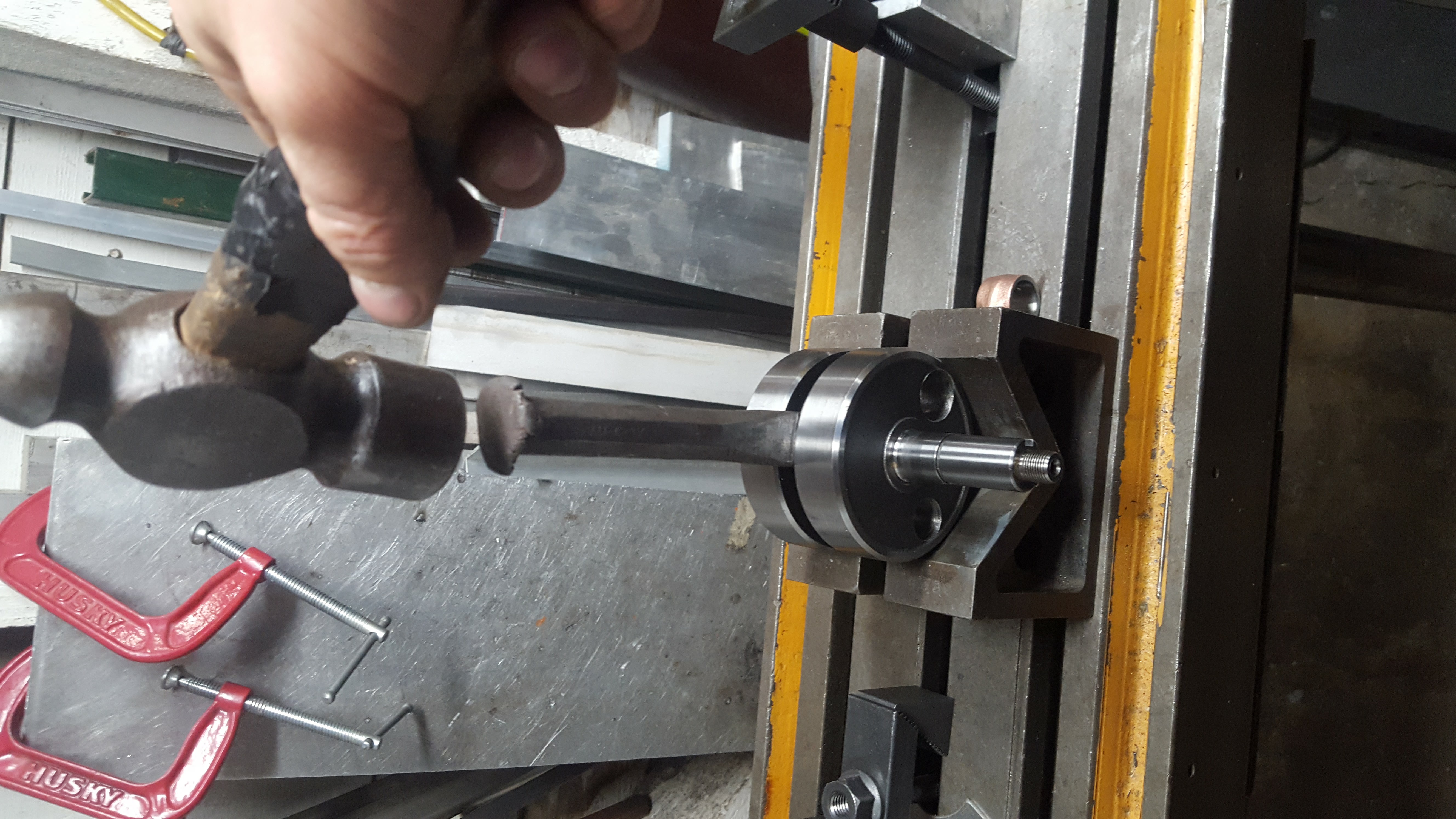
The first step is to remove any main bearings if they are still on the crank. This is done with a bearing separator and a press (Photo 2). The only thing to watch out for here is a bearing that has galled, rusted, or friction welded itself to the shaft, in that case gouging of the spindle can occur rendering it unusable without repair. I like to use an aluminum spacer (press pin) if I have to press against threads on the shaft end (Photo 2, right) as it is less likely, than a steel press pin, to damage them. Similarly, using aluminum press plates (Photo 2, right) is easier on the parts and tools, just make sure that are they are thick plates.
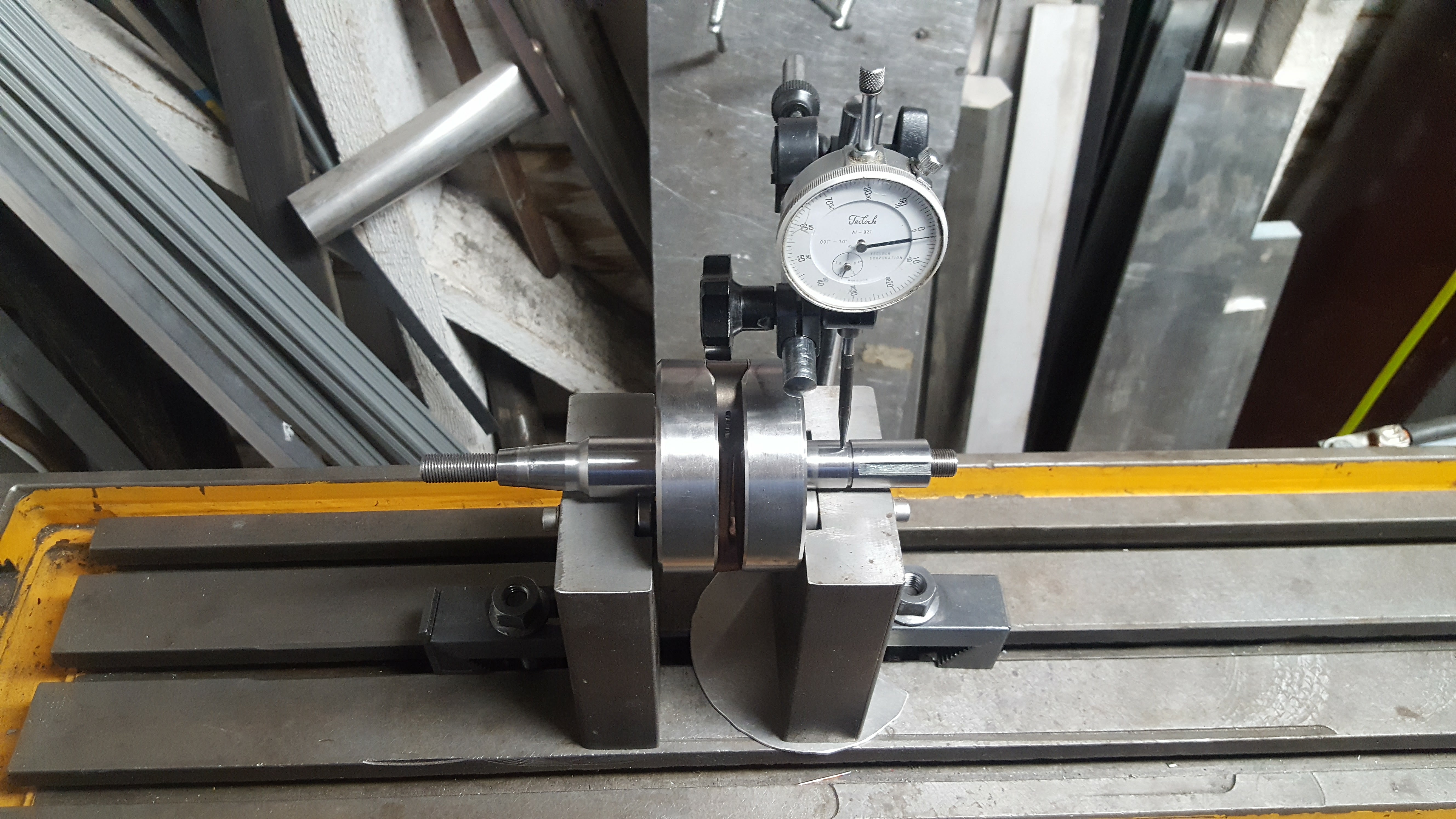
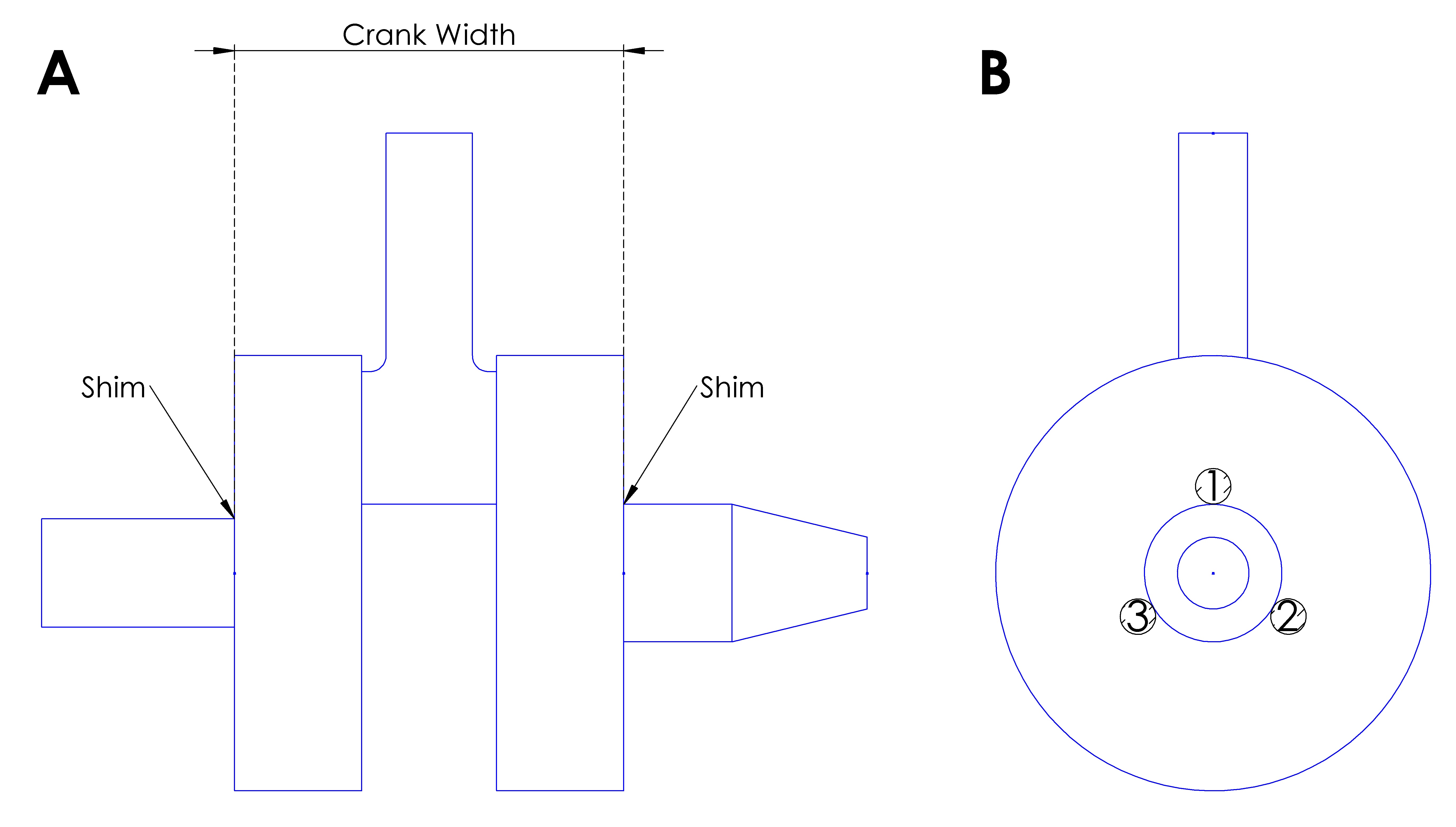 Figure 1. Measurement of crankshaft width. A. front view. B. end view. The width is measured on the flats at the base of the spindles that contact the main bearings. I measure in three places spaced 120 degrees apart (1, 2, and 3 shown in panel B) and average the result.
 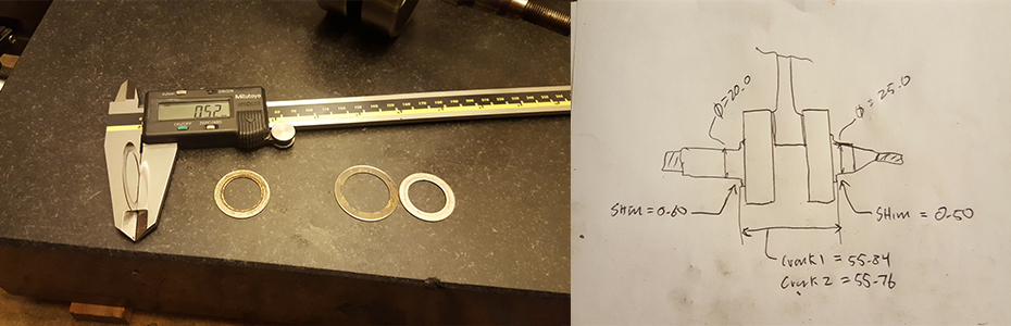 Photo 3. LEFT: Calipers used to measure the crank width and the thickness of the shims (if any). RIGHT: What my shop notes look like for the two DT175 cranks discussed here.
After the main bearings have been removed, I measure the width of the crank (Figure 1). I am measuring the width at the ground flats that contact the main bearings. I measure in three places spaced 120 degrees apart (Figure 1B) and average the result. Measurements are made using a good set of calipers. I prefer the larger 12″ calipers (Photo 3) for this as the smaller more common 6″ ones don’t usually have enough reach to reach the flats. If there are shims at the base of the spindles (as pointed out in Figure 1A) then measure the width of those as well. At this stage all you really need to know is the crank width, as shown in Figure 1A, don’t worry about the clearance of the con-rod big end, you can measure it with a feeler gauge for reference at this point if you like, but you don’t need to know it to proceed. This is because you will never really get the big end clearance and the crank width exactly the same as they were originally, it is more important for them to land in a usable range as discussed later.
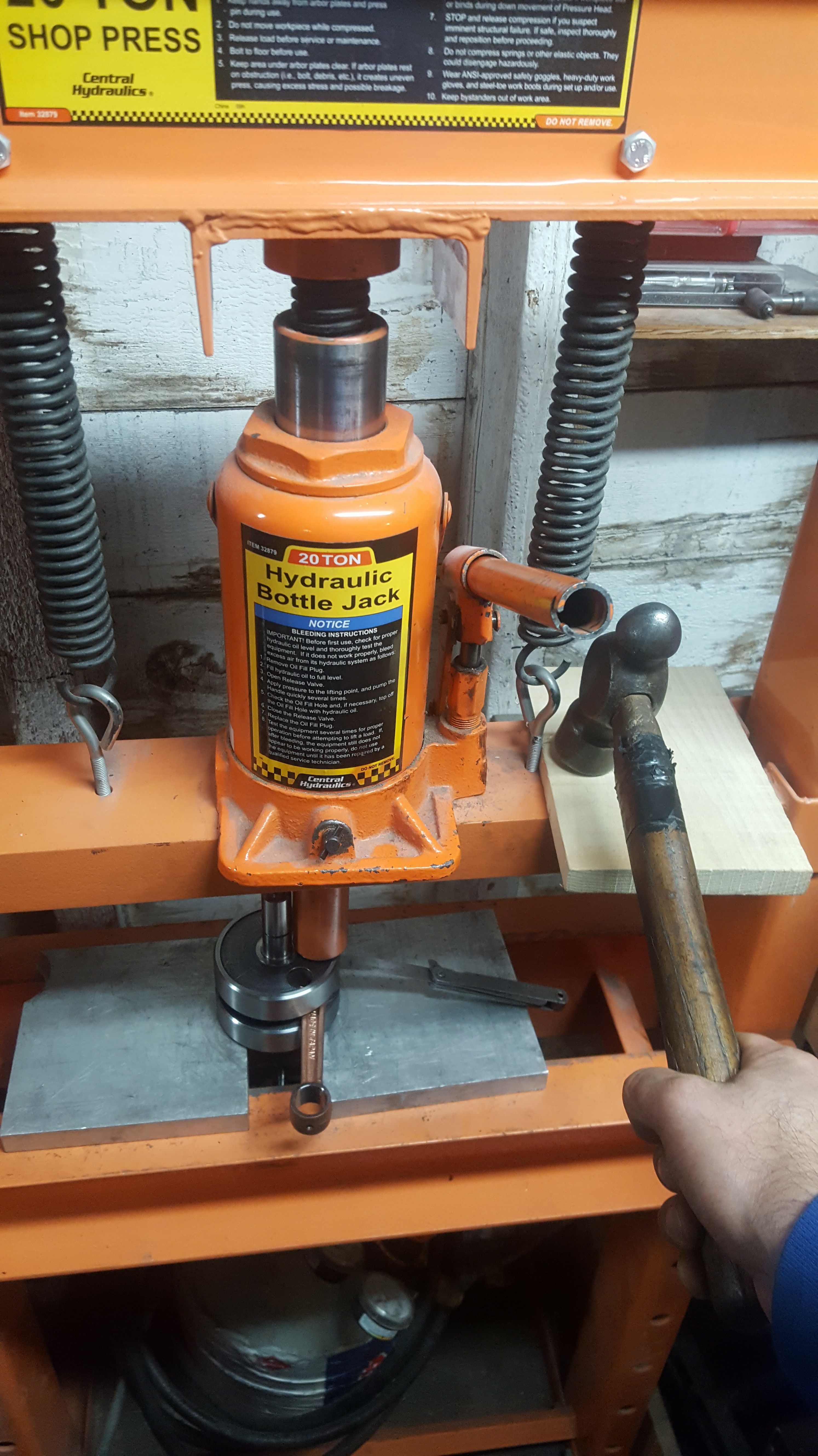
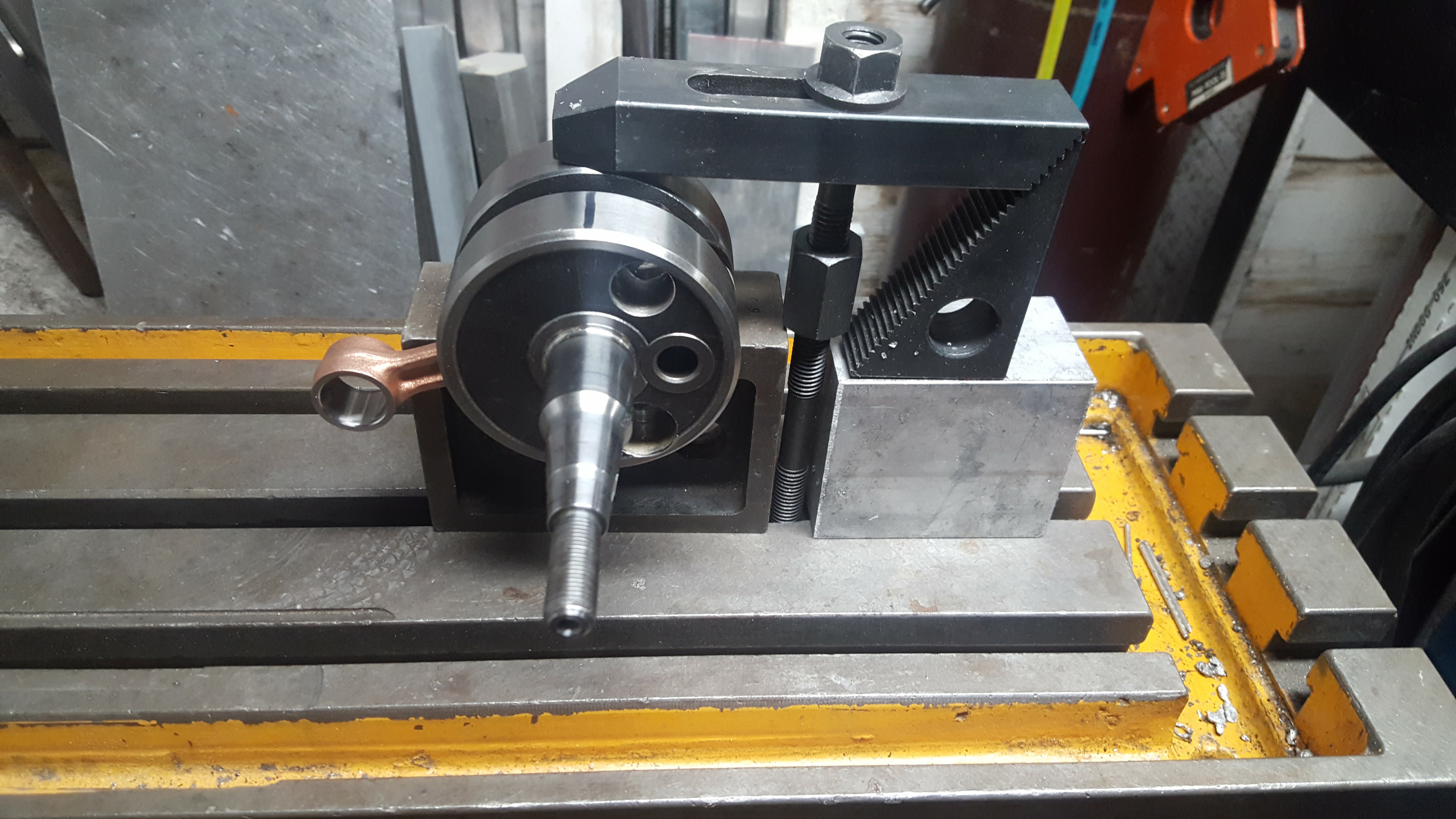
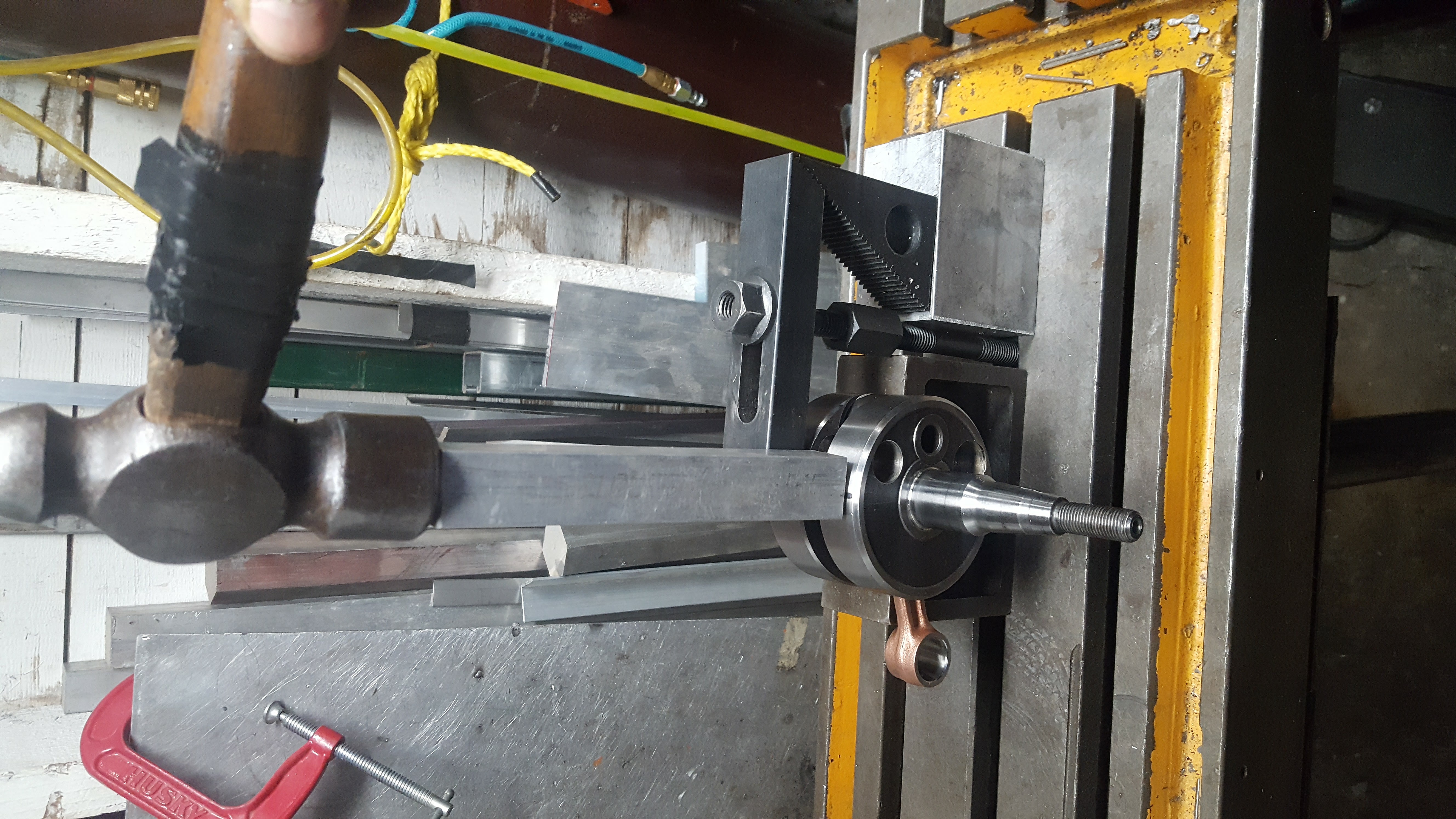
Photo 4. Pressing out the pin, step 1. Left: Simple press set up using 1/4″ thick mild steel plates (angle iron) to support the webs. Right: Loose parts after pressing the pin out of the first web. 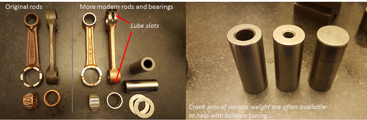 Photo 5. Pressing out the pin, step 2. Left: Simple press setup for removing the crank pin. Old crank and rod pins make great press pins. Right: loose webs after the pin has been completely removed.
The crank pin is pressed out in two stages using a simple 20 ton press (photos 4 and 5). You can easily get buy with a press like this, but a 50 ton press with a more rigid frame would be better, probably more for the rigid frame then for the extra force. I have always meant to reinforce the press in the pictures, but it never seems to take priority over building engines and bikes! Photo 4 shows how pieces of 1/4″ thick mild steel angle iron were used to support the webs, a hardened steel plate is better. Keep in mind the techniques that I am showing here are general techniques that don’t rely on fancy crank-specific fixtures. Most of the jobs I do are unique, so I cant justify making tooling for each crank. Note: old crank and little end pins make great press pins, sockets and extensions also make good press pins.
Photo 6. The webs and spindles are cleaned with a fine or medium Scotch Bright pad while spinning in the lathe.
The free webs are cleaned up with a fine or medium Scotch Bright while spinning in the lathe. At this stage, the spindle can be dressed with fine emery cloth to “tune” its fit into the bearing. I have set up race motors where the ignition side spindle slips easily through the bearing, to make splitting the cases for frequent engine rebuilds easier. Be careful though, don’t go too small, if there is ANY play between the spindle and main bearing the bike will shake like a jackhammer. Generally for a stock rebuild starting from a crank in good shape, just clean the spindle with Scotch Bright only.
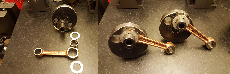
Photo 7. Connecting rods, bearings, big end washers, and crank pins. LEFT: Comparison of the original 1974 Yamaha DT175 rods, and a new production rod with lube holes and an lighter profile. Also note the newer big end bearings with more rollers and a high RPM billet cage. RIGHT: Crank pins of various weight for balance tuning.
Now we can talk rods. Photo 7 show a comparison of the original DT175 rods to some newer design rods that will be installed. The new rods have slots cut in the big end to help get oil to the big end bearing, and a hole in the little end for similar purpose. I will also use a more robust big end bearing that contains more rollers and a billet high RPM silver-plated cage. You can often find crank pins of various weights, having different size holes through the center that can be used if you wish to alter the cranks balance factor. For this build we will use a stock pin as the motor will be largely stock, run in the stock RPM range, and never had a vibration problem, so no need to change.
MORE TO COME!!!!